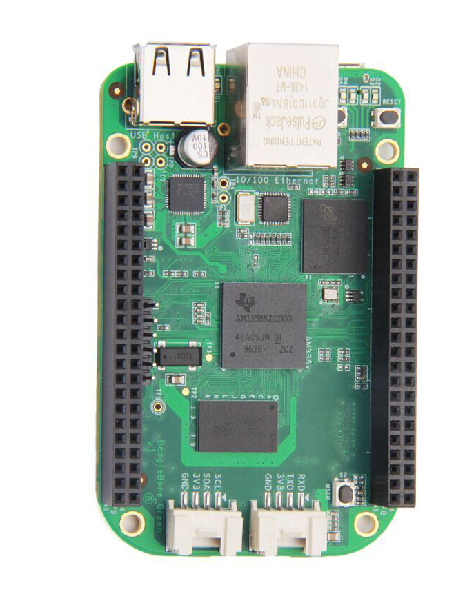
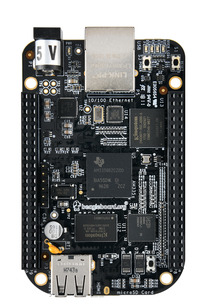
Most of the BeagleBone boards from BeagleBoard.org share the same form factor, have the same headers and therefore can accept the same extension boards, also known as capes in the BeagleBoard world.
Of course, a careful PCB design was necessary to make this possible.
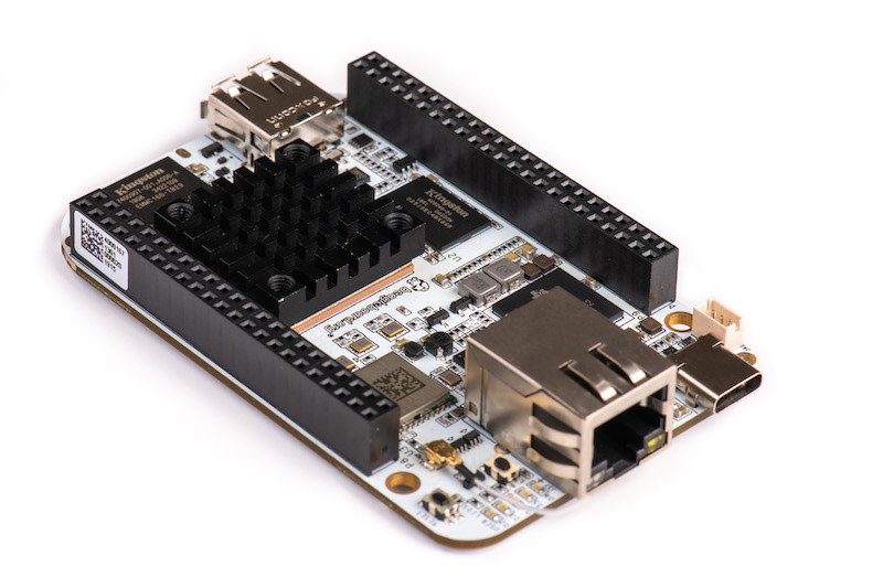
This must have been relatively easy with the early models (BeagleBone Black, Black Wireless, Green, Green Wireless, Black Industrial and Enhanced) which are based on the same Sitara AM3358 System on Chip (SoC) from Texas Instruments. However, the more recent creation (2019) of the BeagleBone AI board and keeping compatibility with existing capes must have been a little more complicated, as this board is based on a completely different SoC from Texas Instruments, the Sitara AM5729.
Once the PCB design challenge was completed, the BeagleBoard.org crew set itself another challenge: implement software that supports each BeagleBone cape in the same way, whatever the board, in particular:
- To have unique identifiers for devices in Linux, so that there is a stable name for Linux devices, even if at the hardware level they are connected differently, depending on whether the base board has a Sitara AM3358 and Sitara AM5729 SoC.
- To have DT overlays for capes that are applicable to all base boards, even if peripherals are connected to different buses of the SoCs.
This article will explore the software solutions implemented by BeagleBoard.org. Their ideas can of course be reused by other projects with similar needs.
The need for a cape standard
A good summary can be found on Deepak Khatri’s Google Summer of Code 2020 page:
The idea of this project was to make the same user space examples work with both BeagleBone Black and BeagleBone AI, using the same references to drivers for peripherals assigned to the same pins between BeagleBone Black and BeagleBone AI. Also, Same DT overlays should work (whenever possible) for both BBB and BBAI, with updated U-Boot cape manager DT overlays will be automatically loaded during boot.
Software setup
The below instructions are for people owning the BeagleBone AI board and any other BeagleBone board, and interested in exploring the devices on their boards by themselves.
First, get the latest console images from https://staging.digitalblender.co/latest-images:
- For BeagleBone AI: AM5729 Debian 10.3 2020-04-06 1GB SD console
- For other BeagleBone boards: AM3358 Debian 10.3 2020-04-06 1GB SD console
Uncompress each image, insert a micro-SD card in the card read in your PC, and then flash the corresponding card. Here are example commands, assuming that the micro-SD card is represented by the /dev/mmcblk0 device:
unxz bone-debian-10.3-console-armhf-2020-04-06-1gb.img.xz
sudo dd if=bone-debian-10.3-console-armhf-2020-04-06-1gb.img.xz of=/dev/mmcblk0 status=progress
Connect the serial line of each board to your computer and then boot each board with it:
- For BeagleBone AI: its sufficient to have the micro-SD card inserted.
- On other BeagleBone boards, you may need to hold a button when you power up the board, to make it boot from the micro-SD card instead of from the internal eMMC. On the BeagleBone Black boards, for examples, that’s the
USERbutton next to the USB host port. Note that you won’t need to do this again when you reset the board. The board will continue to boot from the external micro-SD card until it’s powered off.
You can connect with the default user, or connect as user root with password root.
Then, connect each board to the Internet, and get the latest package updates:
sudo apt update
sudo apt dist-upgrade
It’s then time to upgrade the kernel to the latest version supported by BeagleBoard. To do so, you’ll have to manually update the /opt/scripts/tools/update_kernel.sh file. In this file, go to the # parse commandline options section and add the below lines:
        --lts-5_10-kernel|--lts-5_10)
                kernel="LTS510"
                ;;
You can can then upgrade to the latest 5.10 kernel:
sudo /opt/scripts/tools/update_kernel.sh --ti-channel --lts-5_10
Reboot your board and with the uname -r command, check that you are now running Linux 5.10.
Unifying hardware on AM5729 and AM3358
Let’s start by comparing I2C buses.
Available I2C buses
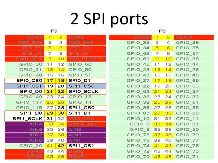
The BeagleBone 101 document has the original P9 and P8 headers specification for I2C for the BeagleBone Black:
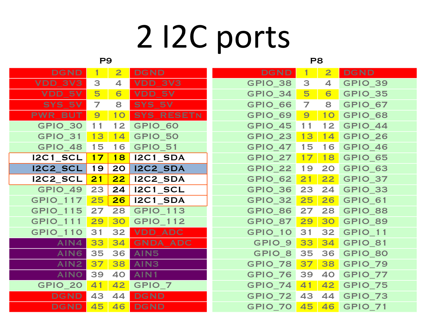
This is confirmed by the BeagleBone Black System Reference Manual. Now, let’s check the BeagleBone AI Reference Manual, which confirms that I2C buses are available at the same P9 connector pins:
| BeagleBone Black | BeagleBone AI | SCL | SDA |
|---|---|---|---|
| I2C1 | I2C5 | P9_17 | P9_18 |
| I2C2 | I2C4 | P9_19 | P9_20 |
| I2C2 | N/A | P9_21 | P9_22 |
| I2C1 | I2C3 | P9_24 | P9_26 |
Note that on the BeagleBone Black, I2C1 and I2C2 are available at two different locations.
So, for both types of boards, we have at least I2C buses on P9_17/18, P9_19/20 and P9_24/26. However, that’s complicated because these pins don’t correspond to the same I2C buses. Therefore, users have to know that P9_19/20 correspond to I2C2 on BeagleBone Black and to I2C4 on BeagleBone AI.
The devices in /dev/ reflect such differences.
Here’s what we have on the BeagleBone AI:
root@beaglebone:~# ls -la /dev/i2c-*
crw------- 1 root root 89, 0 Mar 23 15:00 /dev/i2c-0
crw------- 1 root root 89, 3 Mar 23 15:00 /dev/i2c-3
Note that here with the AM5729 SoC, the first I2C bus is I2C1. Hence, /dev/i2c-0 corresponds to I2C1 (which is another I2C bus available on the SoC but not available through the cape headers) and /dev/i2c-3 corresponds to I2C4. Also note that I2C5 is not exposed in the default configuration that we have here, most probably because the corresponding header pins are used for other purposes.
And now let’s look at what we have on the BeagleBone Black:
root@beaglebone:~# ls -la /dev/i2c-*
crw------- 1 root root 89, 0 Mar 23 16:16 /dev/i2c-0
crw------- 1 root root 89, 1 Mar 23 16:17 /dev/i2c-1
crw------- 1 root root 89, 2 Mar 23 16:17 /dev/i2c-2
Here with the AM3358 SoC, /dev/i2c-0 corresponds to I2C0, /dev/ic2-1 to I2C1 and /dev/ic2-2 to I2C2.
So, on a running system, how to know which I2C bus device corresponds to the P9_19/20 header pins?
Unified access to I2C pins
The I2C section of the BeagleBone Cape Interface Specification, attempts to define equivalent /dev/bone/i2c/[i] bus device symbolic links across the supported CPUs, which correspond to the same cape header pins.
Such symbolic links are specified through the Device Tree description of such buses.
First, let’s have a look at the Device Tree for the BeagleBone AI (arch/arm/boot/dts/am5729-beagleboneai.dts):
&i2c4 {
    status = "okay";
    clock-frequency = <100000>;
    symlink = "bone/i2c/2";
};
Let’s have a look at the corresponding Device Tree for the AM3358 based BeagleBone boards: (arch/arm/boot/dts/am335x-bone-common-univ.dtsi):
&i2c2 {
    status = "okay";
    pinctrl-names = "default";
    pinctrl-0 = <>;

    clock-frequency = <100000>;
    symlink = "bone/i2c/2";
};
You can see that both devices, though they correspond to different devices, share the same symlink property, which is used to create a symbolic link in /dev/bone/i2c/ to the actual bus device file.
Let’s see such symbolic links on the BeagleBone AI:
root@beaglebone:~# ls -la /dev/bone/i2c/
total 0
drwxr-xr-x 2 root root 80 Jan  1  2000 .
drwxr-xr-x 4 root root 80 Jan  1  2000 ..
lrwxrwxrwx 1 root root 11 Mar 23 15:00 0 -> ../../i2c-0
lrwxrwxrwx 1 root root 11 Mar 23 15:00 2 -> ../../i2c-3
And on the BeagleBone Black:
root@beaglebone:~# ls -la /dev/bone/i2c/
total 0
drwxr-xr-x 2 root root 100 Mar 23 16:16 .
drwxr-xr-x 5 root root 100 Mar 23 16:16 ..
lrwxrwxrwx 1 root root  11 Mar 23 16:16 0 -> ../../i2c-0
lrwxrwxrwx 1 root root  11 Mar 23 16:17 1 -> ../../i2c-1
lrwxrwxrwx 1 root root  11 Mar 23 16:17 2 -> ../../i2c-2
You can see that at least /dev/bone/i2c/0 and /dev/bone/i2c/2 are shared between both types of boards. Userspace code examples can then support different boards by referring to such device file links, for example by using the I2C tools commands.
The symbolic links are created from the Device Tree sources not by the Linux kernel, but by the udev device manager, thanks to the following rule found in /etc/udev/rules.d/10-of-symlink.rules in the BeagleBoard Debian distribution:
# allow declaring a symlink for a device in DT

ATTR{device/of_node/symlink}!="", \
        ENV{OF_SYMLINK}="%s{device/of_node/symlink}"

ENV{OF_SYMLINK}!="", ENV{DEVNAME}!="", \
        SYMLINK+="%E{OF_SYMLINK}", \
        TAG+="systemd", ENV{SYSTEMD_ALIAS}+="/dev/%E{OF_SYMLINK}"
Accessing other devices
Other devices are available in the same way through symbolic links in /dev/bone/, for example UART (serial port) devices.
Let’s check on the BeagleBone AI (run sudo apt install tree first):
root@beaglebone:~# tree /dev/bone/
/dev/bone/
├── i2c
│   ├── 0 -> ../../i2c-0
│   └── 2 -> ../../i2c-3
└── uart
    └── 0 -> ../../ttyS0

2 directories, 3 files
On the BeagleBone Black:
root@beaglebone:~# tree /dev/bone/
/dev/bone/
├── i2c
│   ├── 0 -> ../../i2c-0
│   ├── 1 -> ../../i2c-1
│   └── 2 -> ../../i2c-2
├── spi
│   ├── 0.0 -> ../../spidev0.0
│   ├── 0.1 -> ../../spidev0.1
│   ├── 1.0 -> ../../spidev1.0
│   └── 1.1 -> ../../spidev1.1
└── uart
    ├── 0 -> ../../ttyS0
    ├── 1 -> ../../ttyS1
    ├── 2 -> ../../ttyS2
    ├── 3 -> ../../ttyS3
    ├── 4 -> ../../ttyS4
    └── 5 -> ../../ttyS5

3 directories, 13 files
Accessing header pins
Another challenge is with userspace software examples directly refer to header pins by their names. Here is a BoneScript push button demo, for example:
var b = require('bonescript');
b.pinMode('P8_19', b.INPUT);
b.pinMode('P8_13', b.OUTPUT);
setInterval(check,100);

function check(){
b.digitalRead('P8_19', checkButton);
}

function checkButton(x) {
  if(x.value == 1){
    b.digitalWrite('P8_13', b.HIGH);
  }
  else{
    b.digitalWrite('P8_13', b.LOW);
  }
}
For AM3358 BeagleBone boards, the am335x-bone-common-univ.dtsi file already associates the P8_19 name to a specific GPIO:
P8_19 {
    gpio-name = "P8_19";
    gpio = <&gpio0 22 0>;
    input;
    dir-changeable;
};
Such definitions are processed by the drivers/gpio/gpio-of-helper.c driver.
However, this driver is specific to the BeagleBoard.org kernel, and the Device Tree for Beagle Bone AI doesn’t use it yet, so this aspect is still work in progress. The main goal remains though: define generic names for header pins, which map to specific GPIOs on different boards.
Universal Device Tree Overlays for Capes
Another challenge is to implement Device Tree Overlays for BeagleBone capes.
The goal as stated in the beginning is to use the same Device Tree overlays on both types of SoCs. While as of today it doesn’t seem possible to generate compiled Device Tree Overlays (DTBO) which would support both SoCs at the same time, the BeagleBoard.org engineers have come up with a solution to achieve this at source level. This means that, for each cape to support, the Device Tree Overlay binaries for the supported SoCs can be produced from a unique source file.
While this hasn’t been deployed yet in the 5.10 BeagleBoard kernel, such source code is already available in Deepak Khatri’s own tree.
For example this CAN1 overlay (BONE-CAN1.dts):
/*
 * Copyright (C) 2020 Deepak Khatri
 *
 * Virtual cape for /dev/bone/can/1
 *
 * This program is free software; you can redistribute it and/or modify
 * it under the terms of the GNU General Public License version 2 as
 * published by the Free Software Foundation.
 */

/dts-v1/;
/plugin/;

/*
* Helper to show loaded overlays under: /proc/device-tree/chosen/overlays/
*/
&{/chosen} {
    overlays {
        BONE-CAN1 = __TIMESTAMP__;
    };
};

/*
 * Update the default pinmux of the pins.
 * See these files for the phandles (&P9_* & &P8_*)
 * https://github.com/lorforlinux/BeagleBoard-DeviceTrees/blob/compatibility/src/arm/am335x-bone-common-univ.dtsi
 * https://github.com/lorforlinux/BeagleBoard-DeviceTrees/blob/compatibility/src/arm/am572x-bone-common-univ.dtsi
 */
&ocp {
    P9_24_pinmux { pinctrl-0 = <&P9_24_can_pin>;};  /* can rx */
    P9_26_pinmux { pinctrl-0 = <&P9_26_can_pin>;};  /* can tx */
};

/*
 * See these files for the phandles (&bone_*) and other bone bus nodes
 * https://github.com/lorforlinux/BeagleBoard-DeviceTrees/blob/compatibility/src/arm/bbai-bone-buses.dtsi
 * https://github.com/lorforlinux/BeagleBoard-DeviceTrees/blob/compatibility/src/arm/bbb-bone-buses.dtsi
 */
&bone_can_1 {
    status = "okay";
};
The &ocp code applies the pin muxing definitions for CAN on P9_24 (&P9_24_can_pin) and P9_26 (&P9_26_can_pin), which of course are different on AM3358 and AM5729.
Here are these definitions for AM3358 (am335x-bone-common-univ.dtsi):
P9_24_can_pin: pinmux_P9_24_can_pin { pinctrl-single,pins = <
       AM33XX_IOPAD(0x0984, PIN_INPUT_PULLUP | MUX_MODE2) >; };      /* uart1_txd.dcan1_rx */
...
P9_26_can_pin: pinmux_P9_26_can_pin { pinctrl-single,pins = <
       AM33XX_IOPAD(0x0980, PIN_OUTPUT_PULLUP | MUX_MODE2) >; }; /* uart1_rxd.dcan1_tx */
And those for AM5729 (am572x-bone-common-univ.dtsi):
P9_24_can_pin: pinmux_P9_24_can_pin { pinctrl-single,pins = <
        DRA7XX_CORE_IOPAD(0x368C, PIN_INPUT_PULLUP | MUX_MODE2) >; };    /* gpio6_15.dcan2_rx  */
...
P9_26_can_pin: pinmux_P9_26_can_pin { pinctrl-single,pins = <
    DRA7XX_CORE_IOPAD(0x3688, PIN_OUTPUT_PULLUP | MUX_MODE2) >; };   /* gpio6_14.dcan2_tx */
You can see that using a generic Device Tree phandle (&ref), you can use a definition which value depends on the Device Tree includes for each board.
The same idea was applied in enabling (status = "okay";) the CAN1 bus (&bone_can_1).
On AM3358, it is defined as (bbb-bone-buses.dtsi):
bone_can_1: &dcan1 {

};
And on AM5729, its definition is (bbai-bone-buses.dtsi):
bone_can_1: &dcan2 {

};
Conclusion
By adding a symlink property to the Device Tree sources, BeagleBoard.org has made it possible to make userspace code, in particular its code examples, support all the BeagleBone boards at the same time, even though the devices they drive have are numbered differently on different SoCs.
Such a technique may be reused by other projects interested in running the same software on boards based on different SoCs.
As far as GPIOs are concerned, the drivers/gpio/gpio-of-helper.c driver is specific to the BeagleBoard.org kernel and is unlikely to be accepted in the mainline kernel in its current state. However, there are other solutions, supported by the mainline kernel, to associate names to GPIOs and then to look up such GPIOs by name through libgpiod.
Last but not least, it’s possible to use the same Device Tree Overlay source code to support an extension board on similar boards, just by using common definitions having different values on each different platform. Any project can reuse this idea, which just uses standard Device Tree syntax.
References
- Video: Intro: Cape Compatibility layer for BeagleBone Black and BeagleBone AI (Deepak Khatri)
- BeagleBone cape interface spec (elinux.org)
- Cape Compatibility Layer for BeagleBone Black and BeagleBone AI (Deepak Khatri)
- Using Device Tree Overlays, example on BeagleBone Cape add-on boards (BeagleBoard.org blog)
Bootlin thanks BeagleBoard.org for funding the creation of this blog post. Note that another post is coming in the next weeks, about the extension board manager we added to U-Boot thanks to funding from BeagleBoard.org.