The concept of Device Tree overlays
The Device Tree language is a way to describe hardware that is present in a system and cannot be automatically detected. That’s the case of devices directly implemented on a System on a Chip, such as serial ports, Ethernet or Nand flash controllers. That’s also the case of devices connected to a number of buses, such as I2C and SPI, that do not provide mechanisms for dynamic enumeration and identification of devices.
For a given CPU architecture (ARM, PowerPC, etc), such a description allows to have a unique kernel supporting many different systems with distinct Systems on a Chip. The compiled Device Tree (DTB: Device Tree Binary), passed to the kernel by the bootloader at boot time, lets the kernel know which SoC and devices to initialize. Therefore, when you create a new board, and want to use a standard GNU/Linux distribution on it, all you have to do is create a new Device Tree describing your new hardware, compile it, and boot the distribution’s kernel with it. You don’t need to recompile that kernel, at least when it supports your SoC and the devices on your board.
Device Tree Source (DTS) files are normally distributed by kernel developers inside the Linux sources, for example in arch/arm/boot/dts/am335x-boneblack.dts for the BeagleBone Black board.
Kernel developers and board maintainers are not the only ones who may need to make changes to the board device trees, though. Normal users also have legitimate reasons for tweaking the device tree of their board, such as:
- Declaring external devices connected to board connectors. The simplest example is an I2C temperature sensor, but this can also include entire expansion boards plugged into the main board.
- Changing the hardware blocks that are exposed on the external pins of their System on Chip. This is called Pin Multiplexing, and the Device Tree is the place where such multiplexing is configured.
- Modifying operating system related properties, such as the Linux kernel command line or flash partitions.
In you have such a need, a first way to do this would be to directly modify the Device Tree for your hardware in the kernel sources, and recompile it. However, this is a rather bad idea because it will make it more difficult to upgrade to a later version of the kernel, possibly featuring changes to the Device Tree file you modified too. It’s always better not to tweak files maintained by others, and find a way to override them instead.
A second possibility to tweak the Device Tree for a board is to include it from a custom Device Tree for your own use case, using the /include/ statement from the Device Tree language, or #include and the C preprocessor. You can then use references to nodes in the original tree, using labels, and then modify the properties of such nodes or add new subnodes to them. It’s even possible to remove existing nodes and properties by using the /delete-node/ and /delete-property/ statements, as shown in the Device Tree Source Undocumented page.
However, this is still an inconvenient solution. Any time you plug in a new device or an expansion board, or want to tweak other settings, you have to rebuild and update the full Device Tree for your board. What if you could prepare Device Tree fragments for each change to make, compile them once for all, and then, when you boot your device, load the main Device Tree and only the fragments you need, without having anything else to recompile?
This is exactly what Device Tree Overlays are about. For example, in /lib/firmware, the Debian image shipped by BeagleBoard.org contains compiled Device Tree Overlays (DTBO) for the extension boards (also known as capes in the BeagleBoard world) they support, such as:
BBORG_COMMS-00A2.dtbo
BBORG_DISPLAY18-00A2.dtbo
BBORG_DISPLAY70-00A2.dtbo
BBORG_GAMEPUP-00A2.dtbo
BBORG_MOTOR-00A2.dtbo
BBORG_PROTO-00A2.dtbo
BBORG_RELAY-00A2.dtbo
BBORG_TECHLAB-00A2.dtbo
Then, at boot time, all you have to do is load the main DTB for your board, and then override it using the DTBOs corresponding to the capes which are currently mounted. Kernel contributors have also worked on solutions to load the DTBOs dynamically in the live system, but this solution is not mature yet. Therefore, the bootloader based solution at boot time remains so far the best one.
Writing Device Tree overlays
When the Device Tree overlays were first proposed, their syntax was very special and hard to remember. Fortunately, since version 1.5, the Device Tree compiler (dtc) supports a much more natural syntax for writing such overlays. For example, here are the sources for the overlay for the Relay cape, taken from the BBORG_RELAY-00A2.dts file in BeagleBoard.org’s Linux kernel tree:
// SPDX-License-Identifier: GPL-2.0-only
/*
 * Copyright (C) 2015 Robert Nelson
 * Copyright (C) 2019 Amilcar Lucas
 */

/dts-v1/;
/plugin/;

#include <dt-bindings/gpio/gpio.h>
#include <dt-bindings/pinctrl/am33xx.h>

/*
 * Helper to show loaded overlays under: /proc/device-tree/chosen/overlays/
 */
&{/chosen} {
        overlays {
                BBORG_RELAY-00A2.kernel = __TIMESTAMP__;
        };
};

/*
 * Free up the pins used by the cape from the pinmux helpers.
 */
&ocp {
        P9_41_pinmux { status = "disabled"; };  /* P9_41: gpmc_a0.gpio0_20 */
        P9_42_pinmux { status = "disabled"; };  /* P9_42: gpmc_a1.gpio0_07 */
        P9_30_pinmux { status = "disabled"; };  /* P9_30: gpmc_be1n.gpio3_16 */
        P9_27_pinmux { status = "disabled"; };  /* P9_27: mcasp0_fsr.gpio3_19 */
};

&am33xx_pinmux {
        bb_gpio_relay_pins: pinmux_bb_gpio_relay_pins {
                pinctrl-single,pins = <
                        0x1B4 (PIN_OUTPUT_PULLDOWN | MUX_MODE7) /* P9_41: gpmc_a0.gpio0_20 */
                        0x164 (PIN_OUTPUT_PULLDOWN | MUX_MODE7) /* P9_42: gpmc_a1.gpio0_07 */
                        0x198 (PIN_OUTPUT_PULLDOWN | MUX_MODE7) /* P9_30: gpmc_be1n.gpio3_16 */
                        0x1A4 (PIN_OUTPUT_PULLDOWN | MUX_MODE7) /* P9_27: mcasp0_fsr.gpio3_19 */
                >;
        };
};

&{/} {
        leds {
                pinctrl-names = "default";
                pinctrl-0 = <&bb_gpio_relay_pins>;

                compatible = "gpio-leds";

        jp@1 {
            label = "relay-jp1";
            gpios = <&gpio0 20 GPIO_ACTIVE_HIGH>;
            default-state = "keep";
        };

        jp@2 {
            label = "relay-jp2";
            gpios = <&gpio0 07 GPIO_ACTIVE_HIGH>;
            default-state = "keep";
        };

        jp@3 {
            label = "relay-jp3";
            gpios = <&gpio3 16 GPIO_ACTIVE_HIGH>;
            default-state = "keep";
        };

        jp@4 {
            label = "relay-jp4";
            gpios = <&gpio3 19 GPIO_ACTIVE_HIGH>;
            default-state = "keep";
        };
        };
};
This example shows us what is specific to Device Tree Overlay source code, compared to the normal Device Tree syntax:
- Before any definition, the code must include the
/plugin/;statement. - As in normal Device Tree code, you can refer to labels (such as
&am33xx_pinmuxin the above example), modify their properties, add or remove nodes and properties. - However, you cannot modify nodes which do not have a label. In this case, you have to recall such nodes by describing their absolute path from the root device between curly braces. There are two such instances in the above code:
&{/chosen}and&{/}.
Compiling Device Tree overlays
Once you have the source code of the your overlay, it is supposed to be easy to compile it with the Device Tree Compiler. This time, let’s take the example of the BBORG_FAN-A000.dts overlay for the Fan cape, slightly modified:
// SPDX-License-Identifier: GPL-2.0-only
/*
 * Copyright (C) 2020 Robert Nelson
 */

/dts-v1/;
/plugin/;

/*
 * Helper to show loaded overlays under: /proc/device-tree/chosen/overlays/
 */
&{/chosen} {
        overlays {
                BBORG_FAN-A000.kernel = "Tue Jul 14 15:30:00 1789";
        };
};

/* From dra7.dtsi opp_nom-1000000000 */
&cpu0_opp_table {
        opp_slow-500000000 {
                opp-hz = /bits/ 64 <1000000000>;
                opp-microvolt = <1060000 850000 1150000>,
                                <1060000 850000 1150000>;
                opp-supported-hw = <0xFF 0x01>;
                opp-suspend;
        };
};
This file can be compiled as follows:
$ dtc -O dtb -o BBORG_FAN-A000.dtbo BBORG_FAN-A000.dts
The only change we made to this file was to replace __TIMESTAMP__ by a real timestamp. This statement is actually a macro meant to be substituted by the C Preprocesor before compiling with dtc.
This is where real life Device Tree overlay examples are getting more difficult to compile. Very simple overlays can be compiled with the above command, but as soon as the code contains #include statements or macros to be substituted by the C preprocessor, you have to call this preprocessor and give it the path to where the corresponding .h files are found in the kernel sources.
Fortunately, the kernel Makefile knows a suitable series of commands to compile such overlay sources.
Let’s clone BeagleBoard.org’s Linux kernel source tree. It contains Device Tree Overlays for most capes that are compatible with BeagleBoarg.org’s boards, and if I understood correctly, BeagleBoard.org’s kernel developers haven’t solved all the conflicts between their definitions and recent kernels yet. So, let’s checkout their 5.10 branch:
git clone https://github.com/beagleboard/linux.git
cd linux
git branch -a
git checkout 5.10
First, let’s install a toolchain, for example the one on Ubuntu:
sudo apt install gcc-arm-linux-gnueabihf
And then let’s prepare the environment for compiling the kernel:
export ARCH=arm
export CROSS_COMPILE=arm-linux-gnueabihf-
Then, we can configure the kernel for the OMAP SoCs:
make omap2plus_defconfig
We also need to tweak the configuration for compiling the Device Trees and Overlays properly. So, run make menuconfig and set CONFIG_OF_OVERLAY=y. For the practical manipulations, you will also need to set CONFIG_LEDS_GPIO=y and CONFIG_LEDS_CLASS=y.
Device Tree Overlays are found in arch/arm/boot/dts/overlays/. You can compile them along with all normal DTBs with:
make dtbs
In case you want to recompile a specific DT overlay, for example the BBORG_RELAY-00A2.dts file:
$ touch arch/arm/boot/dts/overlays/BBORG_RELAY-00A2.dts
$ make dtbs
  DTCO    arch/arm/boot/dts/overlays/BBORG_RELAY-00A2.dtbo
Of course, for any of this to be useful at the end, you will also need to compile the kernel:
make -j8 zImage
Applying Device Tree overlays
As we already explained, U-Boot is the place where the Device Tree Overlays should be applied. To do this, here are the commands to run in U-Boot. As an example, we’re using the BeagleBone Black and its Relay Cape as example, assuming all the files where copied to the first partition of a micro-SD card, containing a FAT filesystem:
- Load the DTB in RAM:
load mmc 0:1 0x820000000 am335x-boneblack-uboot.dtb
- Let U-Boot know where the DTB was loaded:
fdt addr 0x82000000
- Load the Device Tree Overlay in RAM:
load mmc 0:1 0x83000000 overlays/BBORG_RELAY-00A2.dtbo
- Allocate extra space for the DTB for future overlays, here adding 8192 bytes for example:
fdt resize 8192
- Apply the overlay that we just loaded to the main DTB:
fdt apply 0x83000000
We are then ready to load the Linux kernel and boot it. Let’s see a more complete example…
Example usage on BeagleBone Black
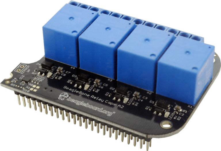
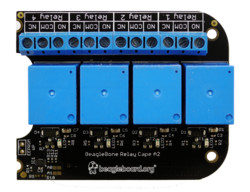
You can of course follow this example, but you can also test it by yourself if you own the BeagleBone Black (or similar BeagleBone boards), and its Relay Cape.
Board setup
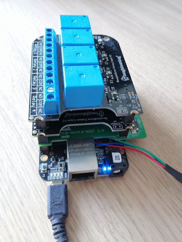
First, connect the Relay Cape to your board. In the below example, more capes are actually stacked, the Relay Cape being on top, as its volume doesn’t allow for further capes:
Then, take a microSD card and format its first partition with the FAT32 filesystem:
sudo mkfs.vfat -F 32 -n boot /dev/mmcblkp1
Remove the microSD card and insert it again. It should now be mounted on /media/$USER/boot. Download an archive containing all the files you should need for the BeagleBone Black and its Relay Cape, and extract this archive in this mount point.
This archive contains U-Boot binaries for the BeagleBone Black, a DTB for the same board, Device Tree Overlays for BeagleBone capes under the overlays/ directory, and a kernel including its own root filesystem as an initramfs. This way, you don’t have to prepare another partition to hold the root filesystem. Note that the src/ subdirectory contains the Buildroot 2021.02 configuration to generate the root filesystem, as well as the Linux kernel configuration that we used.
To boot on U-Boot on the microSD card, press the USER button next to the USB host connector, when you power-up the board. Note that this is needed only once, until the board is completely switched off again. The board will continue to boot from the microSD card across reboots and resets. Make sure that the U-Boot prompt shows a 2021.07 U-Boot version.
Once in U-Boot, you can load the kernel, DTB and DTBO, apply the overlay as shown in the previous session:
load mmc 0:1 0x81000000 zImage
load mmc 0:1 0x820000000 am335x-boneblack-uboot.dtb
fdt addr 0x82000000
load mmc 0:1 0x83000000 overlays/BBORG_RELAY-00A2.dtbo
fdt resize 8192
fdt apply 0x83000000
You are now ready to boot your kernel with its updated Device Tree:
bootz 0x81000000 - 0x82000000
Then, log in with the root user and an empty password.
Checking from Linux that the overlay was applied
The first thing you can check is that the device tree overlay was indeed applied. You can do this by checking properties which are specific to the overlay, such as the one that was added to the chosen node (see the BBORG_RELAY-00A2.dts sources once again.
$ cd /proc/device-tree/chosen/overlays/
$ ls
BBORG_RELAY-00A2.kernel  name
Our overlay specific property is there, but in a more general case, look for properties under /proc/device-tree which are specific to each overlay.
Testing the Relay cape
Have a look again at BBORG_RELAY-00A2.dts file. In particular, for each relay, it declares an LED which is controlled by the same GPIO:
&{/} {
        leds {
                pinctrl-names = "default";
                pinctrl-0 = <&bb_gpio_relay_pins>;

                compatible = "gpio-leds";

        jp@1 {
            label = "relay-jp1";
            gpios = <&gpio0 20 GPIO_ACTIVE_HIGH>;
            default-state = "keep";
        };

        jp@2 {
            label = "relay-jp2";
            gpios = <&gpio0 07 GPIO_ACTIVE_HIGH>;
            default-state = "keep";
        };

        jp@3 {
            label = "relay-jp3";
            gpios = <&gpio3 16 GPIO_ACTIVE_HIGH>;
            default-state = "keep";
        };

        jp@4 {
            label = "relay-jp4";
            gpios = <&gpio3 19 GPIO_ACTIVE_HIGH>;
            default-state = "keep";
        };
        };
};
Each LED is given a label that will correspond to a directory under /sys/class/leds:
# ls /sys/class/leds/relay-*
/sys/class/leds/relay-jp1:
brightness      max_brightness  subsystem       uevent
device          power           trigger

/sys/class/leds/relay-jp2:
brightness      max_brightness  subsystem       uevent
device          power           trigger

/sys/class/leds/relay-jp3:
brightness      max_brightness  subsystem       uevent
device          power           trigger

/sys/class/leds/relay-jp4:
brightness      max_brightness  subsystem       uevent
device          power           trigger
Since the each LED and associated relay are controlled by the same GPIO, this gives us a convenient interface to control the each relay. We just have to control the corresponding LED by using its interface in /sys/class/leds.
This may not be a generic solution to control relays, but it will be easier than having to use the libgpiod library and its associated tools.
Testing a relay for real
Now, let’s try to control Relay 3.
You are ready to connect a real circuit now. When the relay is inactive, the COM (Common) and NO (Normally Open) ports should be disconnected, while COM and NC (Normally Connected) should be connected. When you write 1 to the GPIO, the relay should then connect COM and NO:

The high voltage and low voltage parts of a relay are supposed to be separate and insulated, but in case their was a defect on my cape, I made my tests with a simple low-voltage circuit. However, relays are meant to be used for controlling normal AC voltages (110V / 230V).
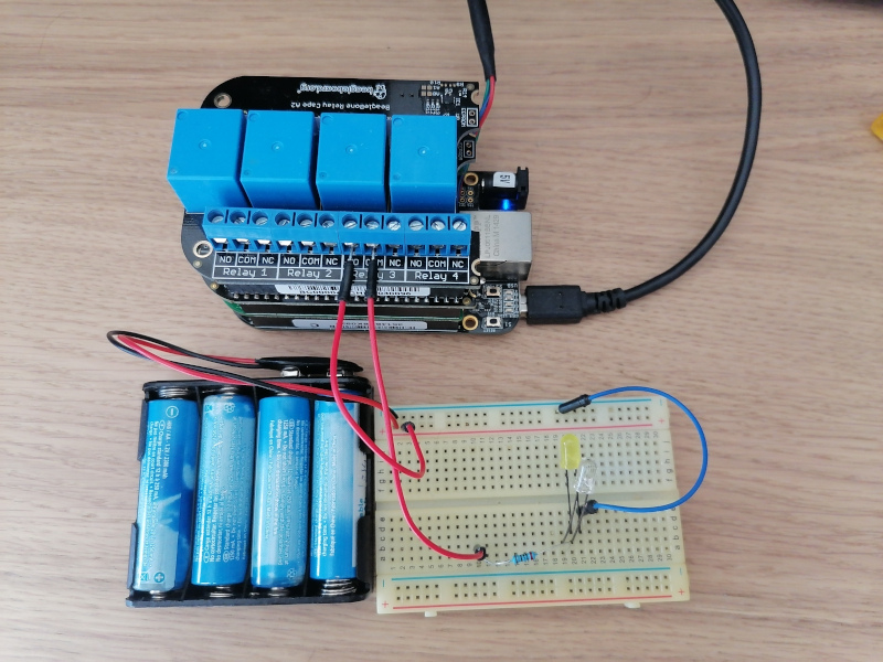
Now, turn on Relay 3 by setting a non zero brightness on the corresponding LED:
echo 1 > /sys/class/leds/relay-jp3/brightness
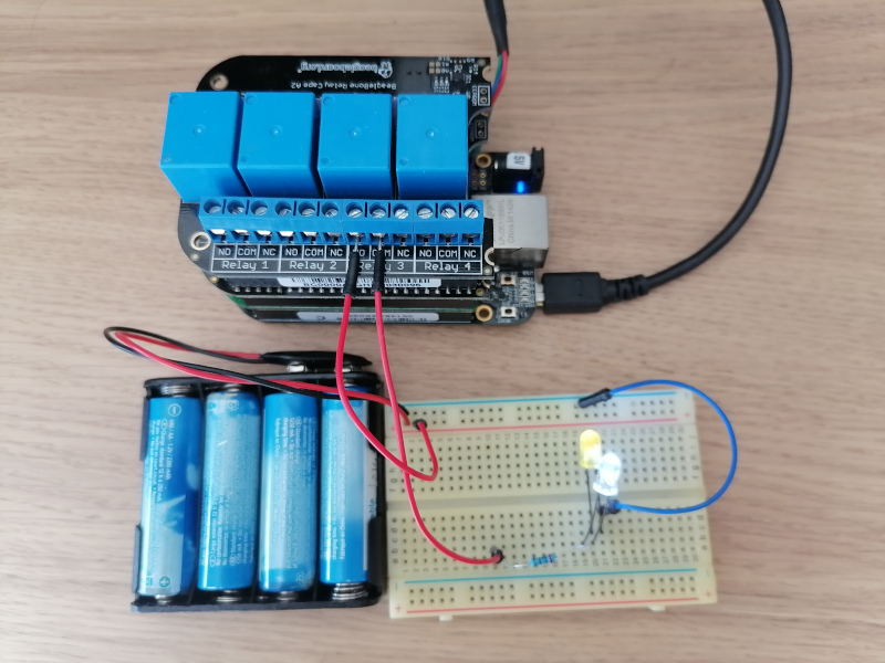
echo 1 > /sys/class/leds/relay-jp3/brightnessYou can turn the relay back off as follows:
echo 0 > /sys/class/leds/relay-jp3/brightness
Don’t hesitate to use this cape in your home automation projects!
What to remember
Device Tree Overlays are Device Tree fragments used to customize the Device Tree of a given board, typically to describe components added externally, including entire expansion boards, or tweak pin multiplexing. That’s the mechanism used by BeagleBoard.org’s kernel developers to support the numerous expansion boards (also known as capes) compatible with their boards. In the bAll you have to do is load the main Device Tree Binary for a board (DTB), and then load and apply Device Tree Overlay Binaries (DTBO).
Bootlin thanks BeagleBoard.org for funding the creation of this blog post. Note that more posts are coming in the next weeks, one about the BeagleBone Cape Interface Specification and one about the extension board manager we added to U-Boot.