(Updated: replaced link to device tree source to point to the overlay for PocketBeagle GamePup cape)
Much has been made of the complexities of the Linux device tree configuration mechanism–it is both a savior and a curse. It saves us from needing to maintain custom kernel logic for every possible board and daughterboard (Cape or PocketCape) setup and curses us with a new syntax to configure all of the specifics of any given chunk of hardware. While the ultimate goal really should be to hide end users from the complexities of this new syntax and the data structures of any given device, even casual users should build up some basic understanding. To that end, please take a look at some of my thoughts below, but don’t feel like you have to understand every word. That is, unless you’ve just developed a new PocketCape and are about to punish reward the world with your amazing new hardware. For those folks, lets work together to make sure users of this rapidly expanding ecosystem have an amazing experience.
First, a bit of a history lesson… From the launch of BeagleBone, we defined in the System Reference Manual a strategy of including I2C-based EEPROMs on all Capes such that those boards could be automatically discovered and appropriate pin configurations could be made. The software implemented by the BeagleBoard.org community, Pantelis Antoniou in particular, to handle Capes ended up not using all of the individual pin configuration details out of the EEPROM, but instead relied on just the board name and version fields identifying a particular set of modifications to the running device tree. The CapeMgr module in the kernel would search for valid EEPROMs and pull the appropriate overlay out of /lib/firmware.
For many hardware developers, the complexity of creating a device tree overlay for their hardware felt too intimidating. To help those developers, the BeagleBoard.org community, Charles Steinkuehler in particular, introduced a concept of a universal Cape that enabled as many drivers as possible and utilized Pantelis’ pinmux helpers to dynamically select which function was routed out to the pins by running some command-line scripts or writing to some sysfs entries. This was eventually merged into the default base board configuration such that no overlay actually needed to be loaded for the dynamic pin configuration and the beaglebone-universal-io config-pin utility is now maintained in a BeagleBoard.org github repo. While this doesn’t automatically configure the hardware for Capes, simple command-line instructions can be used at run-time to talk to the hardware on many Capes or prototype wiring configurations.
Note: One issue with the universal Cape approach is that it locks up some peripherals needed by some other drivers, so we still need to update the device tree.
Another notable change in how BeagleBoard.org Debian images now handle Capes is that device tree overlays are now handled in u-boot. The CapeMgr kernel module has some great benefits for debugging things at run-time and even loading overlays for hardware whose interface isn’t configure until run-time, such as FPGAs or the PRUs. Still, loading the overlays in the u-boot bootloader before the kernel is loaded provides us with the ability to configure LCDs at boot and, perhaps more critically, prevent some drivers from ever even being loaded. While drivers should typically handle the case of being disable, some driver authors simply never handle that case. Besides, loading and then unloading drivers would simply waste time.
For better or worse, not all Capes include the configuration EEPROMs. Even the BeagleBoard.org Robotics Cape, one of our official BeagleBoard.org Capes, is currently without this EEPROM. A configuration file, /boot/uEnv.txt, must therefore be edited to notify the bootloader that a particular overlay needs to be loaded. The potential here is that editing the text file in error can result in your board not booting. Recovering from that error will require you to boot your board by another means, such as via the SD card, USB, or serial. Once booted, you can then mount and re-edit this file to fix your error. I personally do not see many drawbacks of including the Cape configuration EEPROMs on all boards, but cost has been cited as one concern as many of these boards face pricing pressures to make them as affordable as possible.
As of today, the PocketBeagle System Reference Manual doesn’t yet include any detailed recommendations on PocketCape design requirements. Instead, we’ve been watching the best practices of early developers and are seeking to document them. In fact, much of the first available expansion hardware for PocketBeagle comes from the over 250 mikroBUS Click boards already in existence that can be easily wired up to PocketBeagle and for which software support is starting to emerge. The most fundamental aspect of this software support is creating a device tree overlay entry that can be utilized to configure the drivers for the board.
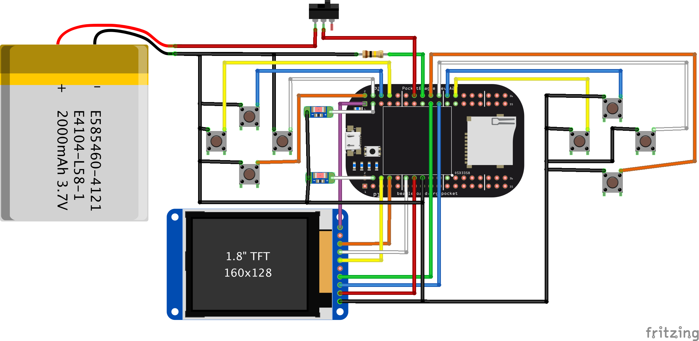
For my example, I’m going to look at the “simple gaming” hack-up board I did for Maker Faire New York. You can find the project entry at bbb.io/+f96db4, but the breadboard view associated with my latest prototype is below.

Ignoring the battery charger for now, for which I haven’t added support, there are 3 key elements requiring drivers: the LCD, the keyboard buttons and the LEDs. Each of these can be tested using run-time configurations, but let’s look at the steps required to create the device tree overlay.
The first thing we must do is free up any of the pins we need from the pinmux helpers. While there are a few different places to find the device tree entries for PocketBeagle, you can always find it in the BeagleBoard.org Github repository for the particular Linux kernel you are using in the provided Debian images. That’s where you’ll find all of the pinmux helpers you’ll need to disable. In the overlay, you’ll see we point the fragment at the “ocp” (on-chip-peripherals) entry one level up the hierarchy from where the pinmux helper drivers are loaded. Then we simply set each of their status entries to “disabled”. While this doesn’t remove these nodes, it prevents the drivers from being loaded.
/*
 * Free up the pins used by the cape from the pinmux helpers.
*/
fragment@0 {
  target = <&ocp>;
  __overlay__ {
    P1_04_pinmux { status = "disabled"; }; /* LEDs - left */
    P2_03_pinmux { status = "disabled"; }; /* LEDs - right */
    P1_06_pinmux { status = "disabled"; }; /* LCD - CS */
    P1_08_pinmux { status = "disabled"; }; /* LCD - SCLK */
    P1_10_pinmux { status = "disabled"; }; /* LCD - MISO */
    P1_12_pinmux { status = "disabled"; }; /* LCD - MOSI */
    P2_01_pinmux { status = "disabled"; }; /* LCD - LED */
    P2_17_pinmux { status = "disabled"; }; /* LCD - DC */
    P2_19_pinmux { status = "disabled"; }; /* LCD - RST */
    P2_02_pinmux { status = "disabled"; }; /* keys - down */
    P2_04_pinmux { status = "disabled"; }; /* keys - right */
    P2_06_pinmux { status = "disabled"; }; /* keys - up */
    P2_08_pinmux { status = "disabled"; }; /* keys - left */
    P2_18_pinmux { status = "disabled"; }; /* keys - enter */
    P2_20_pinmux { status = "disabled"; }; /* keys - one */
    P2_22_pinmux { status = "disabled"; }; /* keys - esc */
    P2_24_pinmux { status = "disabled"; }; /* keys - five */
  };
};
For the next section of the overlay, I could have put part of it in my previous snippet, but I wanted to make sure not to gloss over something that caused me a fair bit of initial confusion. In addition to the pinmux helpers, there are also some gpio helpers loaded to allocate the gpio pins for sysfs. Sysfs exposes the pins directly to userspace programs through the /sys/class/gpio interface. The part that confused me was that these gpio entries are not each specified as individual driver instances, but instead are provided as property nodes for a single instance of gpio-of-helper called cape-universal. That means that I must disable all of cape-universal and create a new instance of it only specifying the gpios that I want to export. Unfortunately, this makes it verbose, but it is fairly simple to copy-and-paste-and-delete the required lines for your hardware. In the code snippet below, I’ve truncated it a bit below for brevity, but you can see the full version in the Github entry. I’m not sure if this will be best for compatibility with userspace applications or not, but, for now, I’ve simply specified the new name as “cape-universal@1” in the hopes that any scripts can simply search for the currently active instance.
/*
 * Free up the gpios used by the cape-universal gpio helpers.
 */
fragment@1 {
  target = <&ocp>;
  __overlay__ {
    cape-universal { status = "disabled"; };
  };
};
/*
 * Make a new set of gpio helpers.
 */
fragment@2 {
  target = <&ocp>;
  __overlay__ {
    cape-universal@1 {
      compatible = "gpio-of-helper";
      status = "okay";
      pinctrl-names = "default";
      pinctrl-0 = <>;

      P1_02 {
        gpio-name = "P1_02";
        gpio = <&gpio2 23 0>;
        input;
        dir-changeable;
      };

      P1_20 {
        gpio-name = "P1_20";
        gpio = <&gpio0 20 0>;
        input;
        dir-changeable;
      };
      .
      .
      .
      P2_35 {
        gpio-name = "P2_35";
        gpio = <&gpio2 22 0>;
        input;
        dir-changeable;
      };
    };
  };
};
Now that we’ve got our gpios back, we can start having some more fun by allocating drivers for our hardware. We’ll start with the LCD. One of the really nice things about using Linux is that for most of the hardware out there, we can probably find a suitable driver for it without needing to code one up from scratch. For SPI and I2C based LCDs, the BeagleBoard.org community, Matt Porter in particular, produced a solution for adding framebuffer support for these displays. This has evolved into the FBTFT project and you can find quite a bit of information on the FBTFT project wiki. It happens that the tinydrm driver in the kernel will be the ultimate home for drivers for these small LCD panels, but the FBTFT project is a good place to start to get something working.
In the snippet below, the first thing I must do is disable the spidev driver instances used to provide userspace access to the SPI peripheral we plan to use for our LCD; I pulled the “channel@0” and “channel@1” names out of the primary device tree. The next thing I do is to create an instance of the SPI driver I want to use with the pin resources, including modes, and properties needed to configure the driver. These properties are often documented for various drivers under the kernel source Documentation devicetree directory, but you can often find good examples exist elsewhere.
/*
 * Free up the SPI port used by the cape and reallocate it for the LCD.
 */
fragment@3 {
  target = <&spi0>;
  __overlay__ {
    #address-cells = <1>;
    #size-cells = <0>;
    status = "okay";
    channel@0 {
      status = "disabled";
    };
    channel@1 {
      status = "disabled";
    };

    adafruit18: adafruit18@0{
      compatible = "sitronix,st7735r";
      pinctrl-names = "default";
      pinctrl-0 = <
        &P1_06_spi_cs_pin   /* CS */
        &P1_08_spi_sclk_pin /* SCLK */
        &P1_10_spi_pin      /* MISO */
        &P1_12_spi_pin      /* MOSI */
        &P2_19_gpio_pin     /* RST */
        &P2_17_gpio_pin     /* DC */
        &P2_01_gpio_pin     /* LED */
      >;
      reg = <0>;
      buswidth = <8>;
      reset-gpios = <&gpio0 27 0>;
      dc-gpios = <&gpio2 1 0>;
      led-gpios = <&gpio1 18 1>;
      debug = <1>;
      spi-max-frequency = <32000000>;
      rotate = <0>;
      bgr;
      fps = <30>;
    };
  };
};
The final overlay snippet simply loads the gpio-keys and gpio-leds drivers for the buttons and LEDs. Sure, you could use the basic gpio userspace driver, but both of these drivers provide some real benefit to end users. The gpio-keys driver produces keyboard events when the buttons are pressed, meaning that I can create keyboard bindings in applications like MAME without needing to modify its source code. The gpio-leds driver enables me to associate many triggers to these new LEDs, again, without needing to write any new code.
Because the overlay has access to the symbols in the primary device tree, I simply reference the pin modes, eliminating the need to look up some register addresses and values. I’ve truncated the detailed setup of the buttons, but you can find the Linux keyboard scancodes by searching the Internet or the kernel source tree.
/*
 * Load the drivers for the buttons and LEDs.
 */
fragment@4 {
  target-path="/";
  __overlay__ {
    gpio-keys {
      compatible = "gpio-keys";
      autorepeat;
      pinctrl-names = "default";
      pinctrl-0 = <
        &P2_02_gpio_pu_pin /* down */
        &P2_04_gpio_pu_pin /* right */
        &P2_06_gpio_pu_pin /* up */
        &P2_08_gpio_pu_pin /* left */
        &P2_18_gpio_pu_pin /* enter */
        &P2_20_gpio_pu_pin /* one */
        &P2_22_gpio_pu_pin /* esc */
        &P2_24_gpio_pu_pin /* five */
      >;
      left {
        label = "left";
        linux,code = <105>;
        gpios = <&gpio1 28 GPIO_ACTIVE_LOW>;
      };
      .
      .
      .
      enter {
        label = "enter";
        linux,code = <28>;
        gpios = <&gpio1 15 GPIO_ACTIVE_LOW>;
      };
    };

    capeleds {
      compatible = "gpio-leds";
      pinctrl-names = "default";
      pinctrl-0 = <         &P1_04_gpio_pin /* left */         &P2_03_gpio_pin /* right */       >;
      led@1 {
        label = "gamingpocketcape::left";
        gpios = <&gpio2 25 GPIO_ACTIVE_HIGH>;
        default-state = "off";
      };
      led@2 {
        label = "gamingpocketcape::right";
        gpios = <&gpio0 23 GPIO_ACTIVE_HIGH>;
        default-state = "off";
      };
    };
  };
};
That’s it! You can see the full file at https://github.com/beagleboard/bb.org-overlays/blob/master/src/arm/BBORG_GAMEPUP-00A2.dts. If you are building and plan to distribute your own Cape or PocketCape hardware, you are strongly encouraged to read and make a Github fork of https://github.com/beagleboard/bb.org-overlays and then submit a pull request to allow users to easily enable and use your hardware.
While we still have a good way to go to fully spell out all the recommendations for PocketCape developers, but this is an important start. We are working to determine if recommending identifying EEPROMs on PocketCapes is the best suggestion for all parties, but knowing that none of the mikroBus Click boards include these mean that it can’t be our exclusive solution.
Before making your PocketCape commercially available, I highly recommend you at least check out the BeagleBoard.org Approved program and engage with our community developers on producing the best experience possible.