Categories: Beginner
I have always wanted to build my own drone, since they are just wildly fun little devices. When I got my hands on a PocketBeagle and was thinking about what my first project was going to be, it didn’t take me long to decide. I wanted to take advantage of the pint sized PocketBeagle make a small (180mm-210mm) quadcopter with the eventual goal of creating a fully functional racer-style FPV model.
Having little to no experience with drones, I started this project with a substantial amount of research. I have included a document at the end of this description with all of the websites I found useful so that other beginners can get a jump start on this part of the process. I quickly discovered that I have a lot to learn on the subject of multi-copters, so the scope of this page is just my first attempts at programming the pocket beagle and getting a couple of motors running. I am hoping to follow up this project with my future attempts to get my from-scratch copter into the air.
After completing my preliminary research, I selected some basic, cheap, components that I checked for compatibility with the pocket beagle. The full list, available above, only ran me about $150. This would have been even cheaper, but I opted to order through Amazon for the expedited shipping.
Most of the components are from this list (
https://fpvdronereviews.com/fpv-racing-drone-budget-parts-list/
), however, I did draw from several other forums and websites to select other parts. Specifically, I needed to select an accelerometer/gyroscope breakout and a altitude/barometer breakout since the PocketBeagle was not intended to be used as a flight control board and does not have these components natively installed. The Hackster page for the PocketPilot (
https://www.hackster.io/patrickpoirier51/pocketpilot-an-autopilot-based-on-the-25-pocketbeagle-1fa14b
) details how to integrate these components with the PocketBeagle on a development board. I believe the eventual goal of that project is creating a single, pre-fab board with all the components, so keep an eye on that page if this interests you.
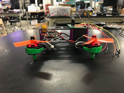
After all my parts arrived, I did some basic assembly work. I constructed the fame, soldered the motors to the Electronic Speed Controllers (ESCs), and attached the motors to the frame arms. This part of the process is very simple, and only requires a basic knowledge of soldering. Be warned, some kits do not come with instructions, however, it is very straight forward and guides can be found online.

The next step I took was getting one of the motors moving. This process was harder because ESCs do not operate intuitively for newcomers. The ESCs take the power from the battery as well as a PWM signal from the control board. I spent several hours trying to figure out why the ESCs were’t turning on, despite receiving a strong signal from the PocketBeagle. Because the ESCs are built to handle a lot of current, operating them can be dangerous. As a result, they require an arming sequence. Below find the manual for the ESCs I was using. It details the signal required to start the motor.
After determining this, I was able to get one motor running. However, one motor is not enough to get any quadcopter off the ground. I needed more motors!
Once again, I ran into the problem of the PocketBeagle not being a dedicated flight control board. Most of the boards I researched had headers designed for the motor control wires. To connect to the PocketBeagle, I had to rig up a small breakout board which allowed me to connect to the 4 different PWM channels. The board connects all of the signal grounds, and routes the PWM signals through the four jumper wires. The connections are made on the back of the board with solder bridges. A detail view can be found in the attached fritzing diagram. Unfortunately, the PWM pins are located far apart on the PocketBeagle and the wiring is subsequently a bit of a mess. I would recommend a dedicated cape for any flight worthy implementation.
From this point, implementing with four motors was relatively simple. All that was needed was a simple copy past in the code and a few variable changes. I also wrote a short shell script that configures the PWM pins and runs the arming code on boot. These files are attached at the end of the page. Additionally, I should note that I preformed all of my coding and uploading in the Cloud9 IDE. This is the recommended interface for the PocketBeagle and detailed instructions for using it with the PocketBeagle can be found on the BeagleBoard website (
https://staging.digitalblender.co/
).
I have not yet gotten all four motors spinning, however, I believe the problem is a hardware issue with the ESCs. I spent a long time debugging/re-soldering every physical connection in the system as well as trying different plug combinations. As a result of this investigation, I determined that the two motors that do spin, work reliably in all combinations of the PWM channels and breakout board headers. I thought the issue might have been due to low amperage, however, isolation of the problem motors didn’t solve the problem. I suspect that the ESCs simply got burned out.
Current state, I have two of four motors running, and all channels functioning. I am working on getting the other two motors running, and I am preparing to design a cape for the PocketBeagle that will hold the instrumentation (Accelerometer and Barometer breakout boards). Below is a video of the motors spinning.
To run this project, you must connect all the drone motors to the control breakout board. Make sure the white wire of the drone harness is on the PWM side (colored wires) of the board. The board must be in turn connected to all of the PWM pins on the pocket beagle (P1_33, P1_36, P2_1, P2_3) and to ground. Any ground pin on the PocketBeagle will work. Once these connections are made, connect the power distribution board to power, to turn on the ESC units. Either a battery with an XT60 connector or alligator clips from a power supply will work. The motors will beep when they turn on. Finally, to start the code and run the motors, apply power to the pocket beagle. On startup the Pocket Beagle will run the code. Details on the connection can be found on the fritzing diagram below.
Please don’t hesitate to contact me with questions/comments/suggestions. I’m super excited to keep developing this drone and learning about the PocketBeagle system.
Comments are not currently available for this post.