Categories: Intermediate
Hello,
Well, I outdid myself this time. I never thought this would work but I kept with it and kept working to make the Motor Bridge Cape work with the correct boards, i.e.
BeagleBoard.org
boards.
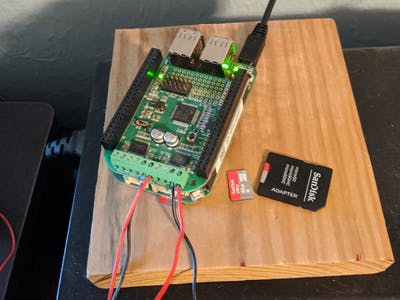
In this case, it is the BeagleBone Green Wireless.
Okay…
Things get complicated and they get complicated quickly in this post. So, if you bear with me, I will show you how to make the Motor Bridge Cape work with your
BeagleBoard.org
board, e.g. Black, Black Wireless, Green, and/or Green Wireless.
So, Seeed Studio put this specific Cape together and it fits snug on the target board, i.e. my BeagleBone Green Wireless.
Enough promotion! Down to business time!
Okay:
Get your image on your board from
beagleboard.org/latest-images.
Then, use these commands to get your board ready:
- sudo apt update
- sudo apt upgrade
- pip3 install smbus2
Once smbus2 is installed, you can view it online or via your board at.local/lib/python3.5/site-packages/smbus2/.
Now, we need to change some lines in the smbus2 directory under the
smbus2.py
file.
So, go to line 302 in the
smbus2.py
library and the line should look this way before you change it:
filepath = "/dev/i2c-{}".format(bus)
Now…in that line, line 302, go and change it to this source:
filepath = "/dev/i2c-2".format(bus)
Now…we need to get some more libraries for your board:
Now, use these commands to navigate:
- cd MotorBridgeCapeforBBG_BBB
- cd BBG_MotorBridgeCape
- nano
MotorBridge.py
Now, we plan on changing some ideas in the source to fit our changed smbus2 library, a move to make one motor move, and to use a direct path for a reset pin that the coprocessor on the Cape uses to communicate.
…
Now:
These lines in the
MotorBridge.py
library need to be changed:
import Adafruit_GPIO.I2C as I2C

import Adafruit_BBIO.GPIO as GPIO

import time


Reset = "P9_23"

MotorBridge = I2C.Device(0x4b, 2)

GPIO.setup(Reset, GPIO.OUT)
The change is made to resemble this idea in the source:
from smbus2 import SMBus

import Adafruit_BBIO.GPIO as GPIO

import time

import pathlib


# reset pin is P9.23, i.e. gpio1.17

reset_pin = pathlib.Path('/sys/class/gpio/gpio49/direction')

reset_pin.write_text('low')


MotorBridge = SMBus('/dev/i2c-2')
Now, we need to change some more ideas in the
MotorBridge.py
library which can be found here:
This…
def WriteByte(Reg,Value):

    data = [0 for i in range(2)]

    data[0] = Reg

    data[1] = Value

    MotorBridge.MotorBridge.write_i2c_block_data(0x4b, 1, data)


def WriteHalfWord(Reg,Value):

    data = [0 for i in range(3)]

    data[0] = Reg

    data[1] = Value & 0xff

    data[2] = (Value>>8) & 0xff

    MotorBridge.MotorBridge.write_i2c_block_data(0x4b, 1, data)


def WriteOneWord(Reg,Value):

    data = [0 for i in range(5)]

    data[0] = Reg

    data[1] = Value & 0xff

    data[2] = (Value>>8) & 0xff

    data[3] = (Value>>16) & 0xff

    data[4] = (Value>>24) & 0xff

    MotorBridge.MotorBridge.write_i2c_block_data(0x4b, 1, data)


def SetDefault():

    WriteOneWord(CONFIG_VALID,0x00000000)
Hello Once More…as you may have seen, I am basically using some libraries and some hardware, just like in English class, where paraphrasing is done. I am sad to say I have not created one of these libraries but I have learned to use them today. This is why I am sharing. I think things deserve to be Open, i.e. open hardware, open source, open software, and open dialog.
…
Okay. So, now we may be thinking that things might or might not work. Who knows? Right? Well, if that did not make your motor move, there must be a reason. I know, I know.
We forgot to use the
MotorBridge.py
library for use in our own source. We need to type up a.py file to use for when we want the motor to move!
Try this!
import MotorBridge

import time


MotorName        = 1

# MotorName        = 2

ClockWise        = 1

CounterClockWise = 2

PwmDuty          = 90

Frequency        = 1000


if __name__=="__main__":

    motor = MotorBridge.MotorBridgeCape()

    motor.DCMotorInit(1, 1000)

    # motor.DCMotorInit(2, 1000)


for i in range(1, 51):

    motor.DCMotorMove(1, 1, 90)

    # motor.DCMotorMove(2, 1, 90)

    print("Making Things Happen!")


for i in range(1, 3):

    motor.DCMotorMove(1, 2, 90)

    # motor.DCMotorMove(2, 2, 90)

    print("Making Things Happen Again!")


for i in range(1, 3):

    motor.DCMotorMove(1, 1, 90)

    print("Done for now?")

    time.sleep(5)
This source should make your motor, one DC motor, turn clockwise, then counter clockwise, and then stop for about 5 seconds before closing the entire program.
As you can see in the source, I have neglected motor #2. This is b/c I am in a test phase with this source and I am only using motor #1.
…
Okay. If that bores you, you can always set up a couple LEDs, a TMP36 temperature sensor, and a couple Servo Motors.
So, TMP36 and breadboard:
- Wire it like this…
- 3.3v (P9_03) of the BBGW to Pin 1 of your TMP36 Temp. Sensor
- GNDA_ADC (P9_34) to Pin 3 of the TMP36 Temp. Sensor
- AIN1 (P9_40) to the Center Pin, Pin 2, of the TMP36 Sensor
Now, we will wire our LEDs and Resistors on the breadboard too:
- Your Anode of the Green LED goes to the resistor and the resistor goes to a hookup wire that goes to P8_13. The Cathode of your LED, the shorter end, goes to a hookup wire that goes to GND on your breadboard.
- Wire the Red LED similar but allow the positive side, your Anode of the LED, to go to the resistor and then to the P8_19 pin via a hookup wire. Make the Cathode go to GND of your breadboard too.
- Now…make a one wire hookup wire go from the breadboard GND, this is where both hookup wires are located on the breadboard from the Cathodes of the LEDS, to the GND pin (P8_01) on your BBGW w/ the Motor Bridge Cape attached.
Now, we can finally put the two Servos on the Motor Bridge Cape servo header pins:
- Use the farthest, most left and the farthest, most right servo connector pins to attach your servos. That is that. Now, we can program this board again but now with a TMP36 sensor to tell us if the temp. is good for motors to turn.
from MotorBridgeI import MotorBridgeCape

from time import sleep

import Adafruit_BBIO.ADC as ADC

import Adafruit_BBIO.GPIO as GPIO


RedLED   = "P8_19"

GreenLED = "P8_13"


GPIO.setup(RedLED, GPIO.OUT)

GPIO.setup(GreenLED, GPIO.OUT)

GPIO.output(RedLED, GPIO.LOW)

GPIO.output(GreenLED, GPIO.LOW)


ADC.setup()


servo_name1 =  1

servo_name6 =  6

frequency   =  50


motor = MotorBridgeCape()

motor.ServoInit(servo_name1, frequency)

motor.ServoInit(servo_name6, frequency)


def motionLED():

    while True:

        reading = ADC.read('P9_40')

        millivolts = reading * 1800

        temp_c = (millivolts - 500) / 10

        temp_f = (temp_c * 9/5) + 32


        if (temp_f >= 81):

        print("Temperature is high %d" % temp_f)

            GPIO.output(RedLED, GPIO.HIGH)

            sleep(3)

            GPIO.output(RedLED, GPIO.LOW)

            sleep(2)

            GPIO.output(GreenLED, GPIO.LOW)

            sleep(5)


        if (temp_f <= 80):

        print("Temperature is normal %d" % temp_f)

            GPIO.output(RedLED, GPIO.LOW)

            GPIO.output(GreenLED, GPIO.HIGH)

            sleep(3)

            GPIO.output(GreenLED, GPIO.LOW)

            sleep(5)


        if (temp_f <= 75):

        print("The temp is below or at %d " % temp_f)

            for i in 0, 180, 0, 135, 0, 90, 0, 45, 0, 90:

            print("The angles are %d: " % i)

                sleep(0.5)

                motor.ServoMoveAngle(servo_name1, i)

                sleep(0.5)

                motor.ServoMoveAngle(servo_name6, i)

                GPIO.output(GreenLED, GPIO.HIGH)

                sleep(2)

                GPIO.output(GreenLED, GPIO.LOW)

                sleep(1)

                GPIO.output(RedLED, GPIO.LOW)

                print("Millivolts accumulate to %d " % millivolts)


motionLED()

sleep(4)

print('Making servos turn with a temp. sensor and some LEDs!')
…
Enjoy.
Oh and you may need to set up this command for P8_19 and set it as a GPIO pin. I think it is a pwm pin by default.
config-pin p8.19 gpio


***************************************************************************************
UPDATE:
Messing w/ a Stepper Motor on a Slide with a Ball Screw…
So, since some items have changed and things are taking place that are out of my control, change the source to suit your needs:
# MotorBridge.py

# These are the items to change out and replace...


from smbus2 import SMBus

import Adafruit_BBIO.GPIO as GPIO

import time

import pathlib


# reset pin is P9.23, i.e. gpio1.17

reset_pin = pathlib.Path('/sys/class/gpio/gpio49/direction')

reset_pin.write_text('low')


...


MotorBridge = SMBus('/dev/i2c-2')


...


def WriteByte(Reg,Value):

    data = [0 for i in range(2)]

    data[0] = Reg

    data[1] = Value

    MotorBridge.MotorBridge.write_i2c_block_data(0x4b, 1, data)


def WriteHalfWord(Reg,Value):

    data = [0 for i in range(3)]

    data[0] = Reg

    data[1] = Value & 0xff

    data[2] = (Value>>8) & 0xff

    MotorBridge.MotorBridge.write_i2c_block_data(0x4b, 1, data)


def WriteOneWord(Reg,Value):

    data = [0 for i in range(5)]

    data[0] = Reg

    data[1] = Value & 0xff

    data[2] = (Value>>8) & 0xff

    data[3] = (Value>>16) & 0xff

    data[4] = (Value>>24) & 0xff

    MotorBridge.MotorBridge.write_i2c_block_data(0x4b, 1, data)


def SetDefault():

    WriteOneWord(CONFIG_VALID,0x00000000)


...


class MotorBridgeCape:

    def __init__(self):

        GPIO.setup("P9_23", GPIO.OUT)

        GPIO.output("P9_23", GPIO.HIGH)

        time.sleep(1)
…
# Stepper.py by


import MotorBridge

import time


def StepperMotorBTest():

    print('Making Servos Act Weird!')

    motor.StepperMotorBInit()

    motor.StepperMotorBMove(10000, 500)

    time.sleep(4)

    motor.StepperMotorBMove(-10000, -500)

    time.sleep(4)


if __name__=="__main__":

    motor = MotorBridge.MotorBridgeCape()

    while True:

        #StepperMotorATest()

        StepperMotorBTest() # Depending on which four wires are connected to your

                            # Motor Bridge Cape
Also: Use this u-boot overlay in the /boot/uEnv.txt file…so it should look this way.
###Overide capes with eeprom

uboot_overlay_addr0=/lib/firmware/BB-I2C-00A0.dtbo

uboot_overlay_addr1=/lib/firmware/BB-UART2-00A0.dtbo


# Also, you may have to disable, if you are using the BBG or BBGW, some items in the

# /boot/uEnv.txt file: Things like >>> disable_uboot_overlay_emmc=1

#                                      disable_uboot_overlay_video=1

#                                      disable_uboot_overlay_audio=1


# Just uncomment the line by removing the hash mark, i.e. '#'.

***************************************************************************************
***************************************************************************************
The correct wiring after a continuity test on two or three wires but who is counting? Oh and the video that follows is not just a bunch of noise and issues. It actually listens to my commands!
This video shows how to not wire your Stepper Motor to the board Cape, i.e. BeagleBone Green Wireless and Motor Bridge Cape. I had to test the leads of the Stepper Motor by putting my DMM (Digital Multimeter) to continuity test on the dial and then listening to if the DMM beeped when I attached the clips to Red and then to the other three wires.
So, I tested like this:
Red – Black, Red – Blue, and Red-Green. Once I received feedback, in the form of a beep on my DMM, when the Red and Blue wires were attached through the DMM, I knew then that those two leads/wires were from the same interior coil on my Stepper Motor. Please wait until later for the next video on an actual productive motion from my slide-ball screw mechanism.
Seth
P.S. Here is the motor moving in case people were wondering about the motor with this simple software. Oh and now you can add your favorite source to the Debian Distro to promote motor movement with your Motor Bridge Cape and BBB, BBBW, BBG, or BBGW:
There is an older song from the Rollins Band in the background. I am sorry but "Ghost Rider!" Come on!
Comments are not currently available for this post.