Categories: Beginner
Background
Kpop fans love to show support for their favorite groups and members through LED light displays (such as the one shown below) that they proudly hold up during kpop concerts. For some fans, this means making a different LED display for every group that they support. But what if the LED display could be changed to show support for a different group with just a press of a button?

As a die-hard kpop fan, I have mixed feelings about these light displays. Do I have to make a new display for each group that I support? As someone who stans upwards of 10 different kpop groups, this is not very feasible. What do I do with the light display after the concert? After putting in all the work needed to create one of these displays, I would hope to repurpose it so that it doesn’t just lay waste in the dust. In designing a new kind of light display, I was motivated to address these concerns. Not only will this new and improved Kpop fan light display allow users to easily switch between light displays for different groups, but the groups’ best hits will also play with the corresponding light display! Fans can jam to their groups’ best hits while enjoying the light display showing their favorite groups’ name, logo, and member names. This display is not only the perfect accessory to have at concerts, but it can also serve as decor to turn any room into a ‘lit’ jam session!
The display will be equipped with 5 buttons color coded to correspond with a particular kpop group. When a button is pressed, that group’s name, logo and member names will scroll across the display while the group’s songs will play continuously in the background. Let the party begin!
Preparing the PocketBeagle
Solder Headers to the PocketBeagle
Parts Needed:
- PocketBeagle
- Dual male headers
- 100 mil female header with short leads
- 100 mil female header with long leads
- Needle-nose pliers
- Wire cutters
- Solderless breadboard
1. Create a jig using the dual male headers. The headers should be the width of the PocketBeagle apart on the breadboard.
2. Using the needle-nosed pliers, pull the middle four pins out of the female headers (both long and short leaded). This should leave 18 leads on either side of the gap.
3. Use the wire cutters to break the headers in half. This should result in four headers with 18 pins each: 2 short leaded and 2 long leaded.
4. Put the headers through the PocketBeagle holes. Ensure that the leads are on the side with the pin labels on the PocketBeagle.
5. Place the PocketBeagle on the jig so that the leads are facing up and the headers are in line and not crooked.
6. Carefully solder each lead.
7. The PocketBeagle can now be removed from the jig and is ready for use.
Audio and Controls
Audio Hardware Build
Parts Needed:
- USB external stereo sound adapter
- Female USB type A adapter
- Speaker of choice
Steps:
1. Solder V_BUS and V_IN pins (P1.5 and P1.7) together.
2. Solder ID and GND pins (P1.13 and P1.15) together.
3. Insert pins of female to USB type A adapter into PocketBeagle header. The pinout is as follows:
Adapter ——————– PocketBeagle
V_cc ——————– V_BUS/V_IN (P1.7)
D- ——————— DN (P1.9)
D+ ——————— DP (P1.11)
ID ——————— ID (P1.13)
GND ——————– GND (P1.15)
4. Plug USB External Stereo Sound Adapter into USB hub connected to the USB end of female to USB type A adapter.
5. Plug speaker of choice into green output port of the stereo sound adapter.
Controls Hardware Build
Parts Needed:
- Push buttons (x 6)
- 1.5 kOhm resistors (x 6; brown, green, red)
Steps:
1. Place button in the middle of breadboard so that there are no connections between the pins on the left and right.
2. Wire the lower right leg of the push button to ground.
3. Wire the upper left leg to a 1.5 kOhm resistor and to a 3.3 V power supply.
4. Also wire the upper left leg to a GPIO pin on the PocketBeagle. The following pins were used in this project (see Fritzing diagram and picture of complete audio and control build below):
Button ————— Pin
Blue ————— P2.17
Red ————— P2.19
Green ————— P2.18
Yellow ————— P2.20
Black ————— P2.22
Control ————— P2.24
Audio and Controls Code
- Ensure that the package for mpg123 (command line mp3 player) is installed. If the player is not installed use both commands in sequential order:
sudo
apt-get install mpg123
sudo apt-get install pulseaudio
- If GPIO pins were wired differently, the constants in the code must be changed to reflect this difference.
- Lists of desired MP3 tracks must be loaded onto the PocketBeagle prior to use. Ensure that the pathway to these lists in the code under the
task
function are complete and correct. - The code for just the audio can also be run through the terminal using
python3
audiotest.py
(make sure pathway includes LEDscape).
LED String Lights
LED String Light Matrix Hardware Build
Parts Needed:
- HKBAYI 240 pixel RGB light string
- Cardboard
- Clear tape
- USB male to 5 pin female adapter
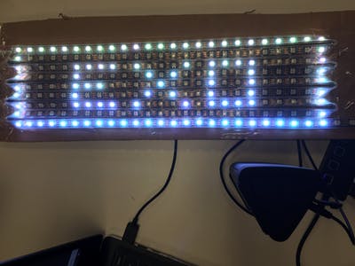
1. Create a 25×9 LED matrix by snaking the LED string down a piece of sturdy cardboard. The ends can be taped down with clear tape. At the end of each row, there will be one light that will not be used in the matrix because it is at the bend of the light string.
2. Connect the female pins to the PocketBeagle and USB hub (for power) using the following pinout:
Wire
————— Pin
Red (Vout) ————— Positive pin of USB
Green (Input) ————— P1.8
White (GND) ————— Negative pin of USB
3. The final build should appear similar to the image below.
LED String Light Matrix Code
- First edit user boot file to use UIO:
cd /boot
grep pru
uEnv.txt
sudo nano
uEnv.txt
- The file should be edited to look like this:
###pru_rproc (4.4.x-ti kernel)
#uboot_overlay_pru=/lib/firmware/AM335X-PRU-RPROC-4-4-TI-00A0.dtbo
###pru_rproc (4.14.x-ti kernel)
#uboot_overlay_pru=/lib/firmware/AM335X-PRU-RPROC-4-14-TI-00A0.dtbo
###pru_uio (4.4.x-ti, 4.14.x-ti & mainline/bone kernel)
uboot_overlay_pru=/lib/firmware/AM335X-PRU-UIO-00A0.dtbo
- Prior to running script, ensure that LEDscape and open pixel control libraries are cloned into user repository. These library contains all scripts needed to drive the LEDs and can be accessed at the links below:
https://github.com/Yona-Appletree/LEDscape
https://github.com/zestyping/openpixelcontrol
- Move all scripts that will be used to operate this device into the LEDscape folder. These include audiotest.py, lightstest.py, Composite.py,
my-config.json
and
opc.py
(from the open pixel control library). - Before running any code, be sure to configure the input pin.
config-pin P1_8 out
- Next begin the server by running:
sudo./opc-server –config
my-config.json
- The code for just the LED display can be run through the terminal using
python3
lightstest.py
(make sure path includes LEDscape).
Instructions for Operation
User should have one terminal open that is used to run
config-pin P1_8 out
and
sudo
./opc-server –config my-config.json.
The user should then open another terminal (without exiting the first) that is used to run
python3
Composite.py
(make sure path includes LEDscape)
.
The user can then interact with the display using the panel of buttons. When switching between groups, the user should press the control button to clear the LED display. Let the continuous music and light displays begin!
Challenges and Next Steps
Challenges
- The most challenging aspect was getting mpg123 to work in a script instead of the command line. Though
os.system
works well for a single song, the multiple inputs from the buttons necessitated the use of
subproccess.Popen
to create a new process when a button is pressed while continuously monitoring the status of the other buttons (i.e. to read input if another button is pressed). - Another challenge was autoboot. Mpg123 uses a jack server that throws an error when trying to use it during autoboot. However, it works fine on the command line. Because of this, I was unable to successfully autoboot my project when PocketBeagle powers up. There is documentation about this issue on online forums. Jack cannot be used with realtime priorities. Further documentation can be found here:
https://askubuntu.com/questions/557906/problem-starting-jack-server-jack-server-is-not-running-or-cannot-be-started
Next
Steps
- Be able to autoboot project when PocketBeagle is powered up and remove need for user interaction with terminal. Use an external battery to power components, so laptop is not needed.
- Be able to switch between groups without having to press the control button to clean display.
- Stream through Spotify to curate a more easily customizable playlist from a larger library of songs.
- Add buffer or use a different audio player since using mpg123 sometimes results in the first few seconds of the song being distorted. This could also be due to hardware issues (poor connections between cables).
- Create a cleaner, more accessible button panel/user interface.
- Add controls for skipping, pausing, or rewinding songs so that player is more flexible.
- Have a selection that is not limited by the number of buttons on the panel. For example, a touch-screen LCD could be used so that user can scroll through a list of groups and select song and light display from that list.
- Refine LED matrix build or figuring out compatibility with pre-made LED matrices such as the Adafruit 64×32 RGB LED matrix.
- Create a convenient carrying case that would contain all the components.
- Create more complex LED displays.
Comments are not currently available for this post.