Categories: Beginner
About
The main goal of the project was to create an easy way to check the temperature and humidity outside without having to take out my phone. In Houston these two pieces of data can change dramatically from day to day and have a huge affect on what I choose to wear in the morning. Yes, I know there are commercial products that do exactly that, but what’s the fun in that? And plus I had this project to do for a class, so two birds, one stone.
My vision for the project was a completely independent device that could sit on my desk and operate without input of connection to a computer. A user can push a single button and then the screen will display the indoor and outdoor temperature and humidity. My device is powered by a 5V battery and can be turned on and off with a switch.
I chose to use the PocketBeagle because it was the most readily available micro-controller to me and it could satisfy all the requirements of my project. I then searched to find the best sensors for measuring the temperature and humidity. I found several analog sensors that could do one of the tasks, but then I found the DHT11 was a digital sensor that could measure both temp and humidity. And it would operate between 3-5 Volts, perfect for the PocketBeagle.
I next searched for a good screen to use. I knew a simple 16×2 LCD display would not have enough characters to tell all the information I wanted in one click, but I also did not need a very large screen to get the point across. The 1.8" Color TFT ST7735R served my needs perfectly and was compatible with the PocketBeagle. My other components were the button and switch which I found lying around the OEDK and are just generic parts. The battery can be any 5V battery from Amazon or you find just lying around.
Wiring
My next step was to determine the proper pin placements to wire the entire device together. I messed up soldering the pins onto my PocketBeagle, so I could not insert it into the bread board, but I could still insert the pins in through the top. For a detailed account of the pins, see the schematic below. In a nutshell, I kept all the pins to one area, on the P2 header. The DHT11’s and the button each got a numbered GPIO pin, and the screen pins were connected to the respective pins shown below. I connected the power rail to the 3.3V output from the PocketBeagle because all of my components could run on that voltage. One of the two temp/humidity sensors was wired directly onto the breadboard with the screen and controller, while the other was wired onto a separate tiny breadboard to act as the outdoor sensor. In theory this sensor could be places outside through a closed window with the wires sticking through. Each sensor and the button were given 10kOhm resistors to act as pull-ups.
I wired everything together and then designed a set of enclosures to contain the device. I wanted it to look cleaner than a jumbled web of jumper wires, while also functioning properly. I arranged all of my exposed components to one corner of the breadboard and made a pair of lids that would just cover the wires and PocketBeagle. Users could still see the screen, press the button, and see the temp/humidity sensor. I also made a box for the outdoor temperature sensor, though it did not fit and will need to be re-sized. Holes in the sides of the boxes allow wires to travel between the boxes. The holes on the tops were made to allow the lids to be screwed on by 3/8" long 4-40 screws. Pictures of my wiring can be seen below in the main container:

My last bit of wiring was to cut a micro USB cord and strip the wires back so I could solder a switch into the middle. I had to determine which of the four wires were ground and power, and then just ignored the other two data cables.
Coding
Once everything was wired and could turn on, I began writing my code. I wrote it right on the PocketBeagle in Cloud9. To operate the temperature sensor, I had to download and install several libraries. These are linked below:
- Pillow:
- Numpy:
With the ST7735R install, you will need the Pocket Beagle connected to the internet so it can pull several additional required libraries on its own. The Numpy download and install will take at least 10-20 minutes to complete.
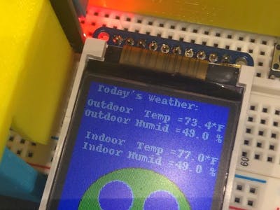
For coding, I chose to use Python because that was the language of the libraries I easily found for my components. I began by playing with the example temperature and humidity codes in the library and adapting them to give me the data from both of my sensors. Once I had that going I set up a configuration file to set up the pin placements for the display on the PocketBeagle. From there I could start playing around with the example codes in the screen library. I made a cat appear, and then some shapes, as you can see in the images above. At this point I copies the example codes for both components into one code and began playing around with the placement of shapes and text on the screen based on the codes numbers. I eventually settled on a text display I liked, and I had some spare space on the screen, so I figured out how to make a face just for fun.
The button was then programmed to initialize the reading in a while loop with several other function for set-up, and initialization created for start up. When the PocketBeagle is turned on, it will automatically load the code attached below and can be used as demonstrated in the video below.
Future
Future adjustments to the project would be as follows:
- Making a new outdoor housing so the breadboard will actually fit
- Testing the device with the outdoor sensor outside through a window
- Making the wires to the outdoor sensor much longer
- Adjusting some hole sizes and placements in the 3D printed boxes to allow for easier use
- Put shrink wrap over the switch to make it look cleaner
Comments are not currently available for this post.