Categories: Beginner
Motivation:
Have you ever wondered how popular your college dorm room is? Having trouble keeping track of how many people are in a room? Worried about breaking fire codes? These questions were constantly crossing my mind and making me lose sleep. That was until I decided to create a device which would be able to tell me! The Guest Counter is a handy device that keeps track of how many people are in a room simply by counting people as they enter or exit! Not only can you get a running count of how many people are in your room, you also get to see how many people have entered or exited your room over the course of a day or even a week.
Overview:
On Startup, the Guest Counter takes about 10 seconds to initialize its hardware and get ready, during which a loading screen is displayed. Once the device is finished initializing, three counters,
Inside
,
Entered
, and
Exited
will appear on the screen and the device is ready to rumble! It is recommended to position the Guest Counter at a doorway at least 3 feet off the ground. Once positioned turn the power on and the device will begin counting. When the device detects a person it will start playing a tone and once that person passes through, the tone will stop. If you press on the push button, the counters on the screen will reset to 0.
Electronics Setup:
The main electronics hardware components are the
Pocketbeagle
, two HC – SR04 Ultrasonic sensors, a Mikroe OLED C display, and a piezo element.
– Pocketbeagle:
For this device I designated all of the different pins I needed to within the code. To get the device to launch the program on startup I did the following steps.
sudo crontab -e
I then scrolled all the way down to the bottom and added in this line of code. I had to make sure to input the correct path for my shell script otherwise the code would not work.
@reboot sleep 30 && sh /var/lib/cloud9/ENGI301/python/project_1/run_guest_counter.sh > /home/debian/bin/logs/cronlog 2>&1
To check if it works:
sudo reboot
–
Ultrasonic Sensors:
The HC – SR04 sensors have 4 connections: GND, TRIG, ECHO, VCC. VCC is a 5V input to power the sensor. TRIG takes an output pulse from the pocketbeagle to tell the sensor when to send out a sound signal. ECHO is a 5V output from the sensor to the pocketbeagle that indicates that the signal has bounced back and been received by the sensor.
I tried a number of different libraries and methods of setting up the ultrasonic sensors. One method is to manually designate the GPIO pins as outputs and inputs and create a function to send a trigger, set a timer, and receive the echo before returning the distance. In addition, there are other outdated libraries floating around online that simply don’t work. As such, this specific library from adafruit gave me very few issues.
The adafruit HC – SR04 library has a function called
distance
which sends out a pulse via the pin connected to TRIG and measures the time it takes to read a voltage from the pin connected to ECHO.
To install the adafruit library enter the following into the pocketbeagle terminal:
sudo pip3 install adafruit-circuitpython-hcsr04
–
Display:
The pocketbeagle has two Mikrobus positions which would technically allow the pocketbeagle to utilize two seperate click boards just by plugging them into the headers on the board. For the Guest Counter, the display is plugged into the "MikroElektronika Click Board 2 Position" as seen in the images below.

To setup the display, I followed instructions from
this hackster
project demonstrating how to use the Mikroe Click boards on a pocketbeagle.
The following is an abbreviated version of the steps described in the url.
First I had to download the "PocketBeagle® OLED-C Click Device Tree Overlay Binary" file called PB_SPI1_OLEDC_click.dtbo (which can be located in the github repository for this project) and upload it to the Cloud9 folder on the pocketbeagle.
– Then copy the file into the /lib/firmware directory
sudo cp PB-SPI1-OLEDC-CLICK.dtbo /lib/firmware/
– Next I had to edit /boot/uEnv.txt to use the device tree file on boot.
sudo nano /boot/uEnv.txt
– Make the following change in nano
###Additional custom capes

uboot_overlay_addr4=/lib/firmware/PB-SPI1-OLEDC-CLICK.dtbo

#uboot_overlay_addr5=/lib/firmware/<file5>.dtbo

#uboot_overlay_addr6=/lib/firmware/<file6>.dtbo

#uboot_overlay_addr7=/lib/firmware/<file7>.dtbo
– Next reboot
sudo reboot
The Hackster project details further steps to check whether the driver was set up correctly.
To actually be able to display images on the display, I downloaded the fbi (Linux Frame Buffer Image-viewer)
sudo apt-get install fbi
The command to display images is:
sudo fbi -T 1 -a NameofImage
Within the code, the os module in python is used to call the above command within the program to change the image.
A unique problem that arises with using this display is that you can only display images on it: you can’t directly send text to be displayed. In addition, while the border of the display is supposed to be 96 x 96 pixels, if you try to display an image of the correct size it will be flipped and offset from the edge of the screen.
To address these problems I had to use the
pillow
library in python. This allowed me to manually draw text onto an image at precise locations, save the image, then flip the image before I sent it to the display.
To install pillow for python, you first have to install its dependencies. Only two of the dependencies are actually required: zlib and libjpeg. For this project I ended up installing all of them using the following bit of code in the terminal.
sudo apt-get install libtiff5-dev libjpeg8-dev zlib1g-dev libfreetype6-dev liblcms2-dev libwebp-dev libharfbuzz-dev libfribidi-dev tcl8.6-dev tk8.6-dev python-tk
Then to actually install pillow:
sudo pip install pillow
When originally testing out the library I had issues selecting a font from the library so I instead downloaded the "arial.ttf" file (can be found in the repository) and put it in the same folder as my code.
Further information regarding usage of the display can be found in the "display.py" file attached.
– Piezo Element
The speaker is connected to a pwm pin and takes an input signal to create sound.
Electronics, Wiring:
Below is the fritzing diagram for the device:
*Note: Display not shown on above fritzing diagram, for wiring instructions for the display see section below.
Mikroe OLED C Display:
The display gets plugged in directly to the pocketbeagle in the Click Board 2 position.
HC – SR04 Connections:
–
Left Sensor:
GND –> GND
ECHO –> P2_4*
TRIG –> P2_2
VCC –> 5V
–
Right Sensor:
GND –> GND
ECHO –> P2_8*
TRIG –> P2_6
VCC –> 5V
*Note: The ECHO output voltage is 5V, however the max voltage of the GPIO pins is rated at 3.3V and can handle up to 3.6V. I used a voltage divider to bring down the voltage to 3.5V
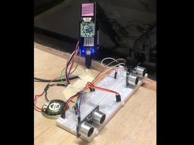
I originally set up the sensors with a voltage divider that would pull the voltage down to 3.3v from 5v, using two 1 kOhm resistors in series as R2 and a 1 kOhm resistor for R1. However, I noticed that there were some inconsistencies in the values being returned by the ultrasonic sensors.
Below is a picture of the original setup:
The new and current setup brings the voltage down to 3.5V as well as separating the two sensors and putting them farther apart.
Speaker Connection
:
GND –> GND
PWM –> P2_1
Button Connection:
GND –> GND
GPIO –> P2_3*
*Note: 1k resistor to 5V,
s
ee fritzing diagram
How It Works:
Step 1: Position the device in front of a doorway
Step 2: Turn the device on
Step 3: Wait for the loading screen to finish and for the counters to display
Step 4: Enjoy!
Issues:
Testing:
The current prototype contains a number of bugs, most of which stem from issues with the ultrasonic sensors. One such issue is that every time the screen updates, it delays the sensors from reading the return signal of a sound and gives back distance readings which are way off. Another source of error is that the ultrasonic sensors need to both be getting readings in order to detect if a person is passing by, but they can’t both be taking readings simultaneously otherwise they would interfere. So in the code, the sensors take readings one at a time, meaning that the device could miss a person walking by.
Enclosure:
A CAD model of the enclosure can be seen below. It contains cut outs for the ultrasonic sensors in the front, cutouts for the screen and a button on top, and a cutout for the power cord on the back. The CAD Files are attached to the project. Unfortunately I did not get to the final step of actually laser cutting the parts of the enclosure.
Future Improvements:
- Laser cut the modeled enclosure that would contain the device and maintain the functionality of the push button, speaker, and not impede the sensor.
- Migrate away from a solder-less breadboard for all of the connections
- Modify the algorithm for determining if w person has passed the device. The current setup involves using one thread to constantly take in values from the sonar, and another thread to check whether something is in the line of sight of the sonar. In addition, a third thread is running in the background updating the values that are being displayed on the device.
- Use a different sensor like a break beam sensor that doesn’t continuously send readings back, but instead simply detects if its path is blocked or not. In addition, the sensor would have to not require communication from the other side of the doorway.
Useful Links:
For Setting up the Ultrasonic Sensors:
https://buildmedia.readthedocs.org/media/pdf/adafruit-circuitpython-hcsr04/latest/adafruit-circuitpython-hcsr04.pdf
For setting up the Mikroe OLED C Click:
https://www.hackster.io/beaglefriends-octavosystems/expand-pocketbeagle-easily-with-mikro-click-boards-oled-c-de7a7c
For using the Mikroe OLED C Click with python:
https://pillow.readthedocs.io/en/stable/
Comments are not currently available for this post.