Categories: Beginner
All of my robots that I have created use a motor controller board similar to the
Rover 5 four channelmotor controller
that I use in
BuddyBot.
These motor controllers are very convenient and easy to use however they can get a little expensive when you are on a budget and want to create multiple robots. Fortunately an H-Bridge is a very cheap alternative to the more expensive motor controllers boards.
H-Bridges
An H-Bridge is an electric circuit that allows us to apply voltage to our motors in either direction allowing the motor to run forwards or backwards. The term H-Bridge comes from the typical graphic representation of the circuit which looks like a capital H. The following image shows how an H-Bridge works.

An H-Bridge is built with four, usually, solid state switches. As we see in the previous image, when switches 1 and 3 (I1 and I3) are open and switches 2 and 4 (I2 and I4) are closed the right side of the motor is connected to the power supply while the left side is connected to ground spinning the motor in one direction. If switches 1 and 3 (I1 and I3) are closed and switches 2 and 4 (I2 and I4) are open then the left side of the motor is connected to the power supply while the right side is connected to ground spinning the motor in the other direction.
For some fun (and this blog post) I created a H-Bridge using four
2n4401 NPN transistors
as shown in the following image:
I am not going to explain how this was built because we do not need to create our own H-Bridges, I just did it for fun (my wife says my idea of fun is a bit weird but what can I say). We can buy them as an IC like the
L293D
which is designed as a motor controller. In this post I will show how to control two motors with the
L293D
H-Bridge motor controller and the BeagleBone Black.
The L293D
The
L293D
is a dual H-Bridge motor driver IC which means that it is capable of driving two motors simultaneously. The following image shows the pin layout for the
L293D
IC.
Since the output from the GPIO ports on the BeagleBone Black is usually not enough to drive our motors, the
L293D
has both a Vcc (3.3V from the BeagleBone Black) and a Vmotor (power for the motors 6V->12V). The L293D also has two enable pins which should remain high to enable the motors. If the enable pins are low the H-Bridge will be disabled.
Each side of the IC has two inputs and two outputs. Each of the inputs should go to a separate GPIO pin on the BeagleBone Black. To make the motor turn in the forward direction one input should be high and the other input low. To make the motor turn in the reverse direction we should reverse which pin is high and which pin is low. As an example if we are using the left side of the IC for our motor we could set IN1 to high and IN2 to low to drive our motor in one direction and then set IN1 low and IN2 high to drive our motor in the other direction. The OUT1 and OUT2 pins should be connected to the DC motor that we are trying to drive.
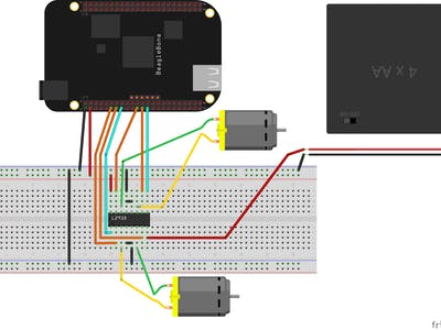
The L293D has four GND pins. All four GND pins need to be connected to a ground even if you are only driving one motor with the IC. The following diagram shows how I have the L293D connected to my BeagleBone Black to drive two motors:
As you can see we are using six GPIO pins to drive our two motors. Pins 15 and 25 of the P9 header are connected to the enable pins on the L293D IC. Both of these pins will need to be high to enable the motors. We have pins 11 and 13 of the P9 header connected to the IN1 and IN2 pins on the IC. We also have pins 21 and 23 of the P9 header connected to the IN3 and IN4 pins.
The DC motors that we are driving with the L293D are connected to the OUT pins of the IC. To drive the first motor we will use the following table to see how we should set pins 11, 13 and 15.
Pin 11 (IN1)      Pin 13 (IN2)     Pin 15 (Enable1)  Result

High              Low              High               Motor spins one direction

Low               High             High               Motor spins other direction

High              High             High               Stopped

Low               Low              High               Stopped

X                 X                Low                Stopped
The same table can be applied to the second motor as well, just substitute pins 11, 13 and 15 with pins 21, 23 and 25.
How to program it
Now how can we program this with Swift. For the
SwiftyBones library
I wrote a component called
SBHBridge
That makes it very easy to add an H-Bridge to your project. You would create an instance of the
SBHBridge
type like this:
var leftMotor = try SBHBridge(forwardHeader: .P9, forwardPin: 11,

                          reverseHeader: .P9,reversePin: 13,

                          enableHeader: .P9,enablePin: 15,

                          componentName:"Left Motor")

var rightMotor = try SBHBridge(forwardHeader: .P9, forwardPin: 23,

                          reverseHeader: .P9,reversePin: 25,

                          enableHeader: .P9,enablePin: 27,

                          componentName:"Left Motor")
Now we can spin the motor in the forward direction like this:
                         leftMotor.goForward()

                         rightMotor.goForward()
Or in the reverse direction like this:
                         leftMotor.goReverse()

                         rightMotor.goReverse()
We can also enable or disable the motor using the
enableMotor(Bool)
function:
                         leftMotor.enableMotor(true)

                         rightMotor.enableMotor(true)
Adding an H-Bridge to your robotics project is a cheap and simple way to drive your motors. The
SwiftyBones library
makes it incredible easy to use it with your next project.
Comments are not currently available for this post.