Categories: Intermediate
Our project involves interfacing with six LED matrices and audio input. The goal is to take the audio input, perform a frequency domain analysis, and then display the frequency spectrum onto the LED matrices as a spectrometer.
We managed to get audio input and perform frequency domain analysis on the host computer. The host is then sending pixel data to the pocket beagle that is using falcon player to control the LED matrices and create an audio spectrometer.
Check out the project in action at:
Also check out our Wikipedia Project Page at:
https://elinux.org/ECE434_Project_-_LED_Matrix
Step One: Hardware Setup
We were fortunate enough to have received the LED Panels already placed together when we received them. To link the LED panels, align the arrows on the back of the panel so that they all face the same directions and then connect each panel to the one adjacent to it horizontally. The last two panels will connect to the PocketScroller Cape of for the PocketBealge. The PocketBeagle connects directly into the PocketScroller Cape.
Step Two: Installation
Go to
https://github.com/grinstba/LEDMatrix
and clone the repository to your computer
Go to
https://falcon-player.gitbooks.io/falcon-player-manual/content/chapter_three_installation/downloading_the_falcon_player.html
and follow the instruction to download the latest falcon player image and then flash it to one of your SD cards. Make sure to download the Beagle Bone image and not the Raspberry Pi image. Also, we were not running the falcon player off of eMMC.
Once falcon player is installed, boot up your Beagle Bone and ssh into it with the following credentials:
- username: fpp
- password: falcon
By default the image we are running doesn’t allow a root login. You will need a root login in order to get internet access on the Beagle Bone. In order to setup internet access, first ssh into the Beagle Bone with the default username and password listed above. The root access directions below are modified from
https://elinux.org/EBC_Exercise_02_Out-of-the-Box, _Bone
Then run the following commands on the Beagle Bone
bone$ sudo bash

root@bone# nano /etc/ssh/sshd_config
Search for the line
#PermitRootLogin prohibit-password
and change it to
PermitRootLogin yes
Save the file and quit the editor. Restart ssh so it will reread the file.
root@bone# systemctl restart sshd
And assign a password to root.
root@bone# passwd
Now open another window on your host computer and enter:
host$ ssh-copy-id root@bone
and enter the root password. Test it with:
host$ ssh root@bone
You should be connected without a password. Now go back to the Bone and turn off the root password access.
root@bone# nano /etc/ssh/sshd_config
Restore the line:
#PermitRootLogin prohibit-password
and restart sshd.
root@bone# systemctl restart sshd

root@bone# exit

bone$ exit
Now, on your host run the following command to get network information:
host# ip -a
For us, on a WiFi network running the
ipMaskquerade.sh
script in the following way works: and restart sshd.
host# ./ipMaskquerade.sh ens33
Then run the
firstssh.sh
script
host# ./firstssh.sh
Once connected to the the internet, go ahead and clone our GitHub project onto the pocket beagle from
https://github.com/grinstba/LEDMatrix
.
Once the projected has cloned, run the
install.sh
script to install the needed packages for the project to run.
Step Two: User Instructions
Many of the following images and directions come from Mark A. Yoder’s documentation found
here
In order to light up an entire 32×64 LED panel white (Red, Green, and Blue all on), you will need at least a 5V 4A power supply. Each panel has a single power connection and a data in and data out connection. The data in connections control how the panel operates and the data out connections allow you to daisy chain the panels together to created a large display. The image below shows the connection.

https://markayoder.github.io/PRUCookbook/01case/case.html#case_rgb_matrix
Once the falcon player image has been flashed to an SD card, insert the SD card into your Beagle Bone and connect it to a host computer via USB cable. Browser to
https://192.168.7.2
and you will see the falcon player control panel shown below.
https://markayoder.github.io/PRUCookbook/01case/case.html#case_rgb_matrix
You can use the settings in the control panel to set up the orientation of the LED Matrix. First switch the FPPD mode on the status page to bridged as shown below.
https://github.com/grinstba/LEDMatrix
/blob/master/Setup/StatusPageBridgeSetup.PNG
Then, navigate to the Input/Output Setup tab and click on "Channel Inputs". Configure 96 input channels to have a universe size of 384 as shown in the picture below.
https://github.com/grinstba/LEDMatrix
/blob/master/Setup/UniverseSetupInputChannels.PNG
In the same Input/Output Setup tab, click on "Channel Outputs". Configure 96 output channels to have a universe size of 384 as shown in the picture below.
https://github.com/grinstba/LEDMatrix
/blob/master/Setup/UniverseSetupOutputChannels.PNG
Next, under the Input/Output Setup tab, navigate to "LED Panels". This is where you set up the way in which the Output Universes will be represented on the physical LED Panels. Set the Panel Layout to 2X3, the Single Panel Size to 64X32 1/16 Scan, and the Panel Gamma to 2.2. You may choose the brightness that you desire. The Color Depth is 8 bit and the connection is the Hat/Cap/Cape. The color layout of the LED Panels are RGB, meaning that each little square of light on the panel has 3 channels; a red channel, green channel, and blue channel. This means that in total there are 64X32X3 = 6144 channels per panel. Since we have 6 panels, we have 6144X6 = 36864 total channels. Set the wiring pinout to PocketScroller. Looking at the LED Panel Layout section, leave "View Config from front?" checked. Since the panel layout is 2X3, we have two physical output numbers and 3 panel numbers for each physical output. The left column of the "Front View" should be set to O-1 for each row with P increasing from 1-3 as you go from top to bottom. The left column of the "Front View" should be set to O-2 with P increasing from 1-3 as you go from top to bottom. The arrows should be pointing from the right column to the left column for each row. All of these settings are shown below in the figure. After inputting all of these settings, click save, and then click on the "Restart FPPD" at the top of the screen in the red box. Look at the arrows shown on the back of the physical LED Matrix to determine which way to place it so that its configuration matches the direction that you just set it up as on the Falcon Player. In order to match this setup, you want the horizontal arrows going from right to left and the vertical arrows pointing from top to bottom.
https://github.com/grinstba/LEDMatrix
/blob/master/Setup/LEDPanelSetup.PNG
With the LED Matrix set up in this way, the bottom ribbon cable will connect into J1, and the top ribbon cable will connect into J2 on the PocketScroller. Power up the LED Matrix. At this point, within the Falcon Player you can navigate to Status/Control and click on the "Display Testing" tab. Set the end channel to 36864 and then select the checkbox that says "Enable Test Mode" as shown below.
https://github.com/grinstba/LEDMatrix
/blob/master/Setup/DisplayTesting.PNG
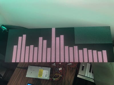
At this point, if everything is configured correctly, the LED Matrix should light up as shown below. It is possible that if you choose a testing mode that turns on every single channel on the matrix, the Power Supply will not be able to keep up with the load and the matrix could shut off.
https://github.com/grinstba/LEDMatrix
/blob/master/Setup/DisplayTestingPhysicalMatrix.jpg
Click on the "Enable Test Mode" checkbox to stop testing the display. You are now ready to run the spectrogram program. Navigate to where the LEDMatrix git repository is cloned on your local drive. Then run Spectrogram.py.
Step Three: Theory of Operation
A general overview of how our project works is shown in the figure below. A speaker outputs sound that is picked up by the microphone from our laptop. This audio signal is then processed to obtain its amplitude vs frequency. We then use this information to decide on the height of our LED bars which is communicated to the PocketBeagle from the host computer.
https://github.com/grinstba/LEDMatrix
/blob/master/Setup/Operation%20Overview.jpg
Looking more closely at our software, the following figure breaks down the logic flow. First we have to set up our connection with the Falcon Player that is running on the PocketBeagle. Then we set up the audio processing parameters and universe sizes for the LEDMatrix. Once these are set up, the program is constantly listening for audio input, performing a Fast Fourier Transformation on the audio to give us the amplitude vs frequency information, dividing these values into our specified ranges, converting these amplitude values to LED channel information for the universes, and sending the LED information to the PocketBeagle.
https://github.com/grinstba/LEDMatrix
/blob/master/Setup/Software%20Operation.jpg
In order to better understand how we are utilizing the universes to control the matrix, we created the following figure. We chose the universe size so that each universe is two full vertical columns of LEDs. In total this means there are 96 universes from left to right. Our software starts on the left hand side with universe 1, and ends on the right hand side with universe 96. We specify each bar in our spectrogram to be 3 universes wide, or 6 columns of LEDs wide. As a result, we have the potential for 26 bars on the matrix. In order to make it look nicer and easier to see the separation between bars, we only utilize 21 bars and leave a universe between each bar that we don’t write data to. Since the universes wrap around from top to bottom, each time an amplitude is calculated, zeros must be padded into the universe in order to make sure that both columns within the universe maintain the same height on the matrix.
https://github.com/grinstba/LEDMatrix
/blob/master/Setup/Panel%20Theory.jpg
Conclusions:
In the end, this project was an interesting challenge that provided us with the opportunity to test our signal processing skills and learn about how to configure, control, and reliably update the LED Matrix. Some fun potential additions could include detecting a song’s BPM(beats per minute) using the audio signal and updating the bars colors or other patterns to the exact BPM of the music as opposed to it updating just amplitudes of the frequency ranges.
Comments are not currently available for this post.