Categories: Advanced, BeagleBone AI, Music, PocketBeagle
Ever wanted to record audio from 16 PDM microphones simultaneously? Now you can with a BeagleMic running on PocketBeagle or BeagleBone AI. No external active components are used. Instead the PRU subsystem takes care of all the magic:
- Generating the PDM clock.
- Latching serial data from all 16 microphones.
- Running CIC filters for each audio channel in order to convert PDM into PCM.
- Storing PCM samples in a shared region of the system DRAM memory. Current firmware supports two modes of operation. Either 16 channels and 16 bits per audio sample, or 8 channels with 24 bits per sample.
| Feature                    | 16 Channel Mode   | 8 Channel Mode    |

|----------------------------|-------------------|-------------------|

| PDM Bit Clock              | 2,273 MHz         | 3,448 MHz         |

| PCM Output Bits Per Sample | 16 bps            | 24 bps            |

| PCM Output Sample Rate     | 31888 Samples/sec | 26940 Samples/sec |
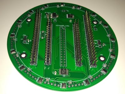
The Hardware
The schematic is simple. PDM microphones’ digital outputs are connected directly to the PRU input pins. The PRU also drives the bit clock. Optionally, simple buffer gates SN74AUC2G34 can be used to alleviate the single PocketBeagle pad from driving 16 clock inputs simultaneously.
| PocketBeagle | BBAI  | PRU Pin | Type  | Signal               |

|--------------|-------|---------|-------|----------------------|

| P2.24        | P9.11 | R30_14  | Output| PDM Bit Clock        |

| P1.36        | P8.44 | R31_0   | Input | MIC0 and MIC1 Data   |

| P1.33        | P8.41 | R31_1   | Input | MIC2 and MIC3 Data   |

| P2.32        | P8.42 | R31_2   | Input | MIC4 and MIC5 Data   |

| P2.30        | P8.39 | R31_3   | Input | MIC6 and MIC7 Data   |

| P1.31        | P8.40 | R31_4   | Input | MIC8 and MIC9 Data   |

| P2.34        | P8.37 | R31_5   | Input | MIC10 and MIC11 Data |

| P2.28        | P8.38 | R31_6   | Input | MIC12 and MIC13 Data |

| P1.29        | P8.36 | R31_7   | Input | MIC14 and MIC15 Data |
Optionally, high-level software may visualize detected audio direction using a stripe of 16 LEDs hooked to two 74HC595 shift registers.
For each microphone pair, one microphone is configured to output data on the rising clock edge, and the other is configured to output data on the falling edge. This way we need only 8 input PRU GPIOs to capture data from all 16 microphones. The PocketBeagle Cape was designed using KiCad and full source is provided.
The Manufacturing
The hardest part of the project for me was soldering the microphones. That says a lot, given the long sequence of code-generating assembler macros in PRU0 firmware.
The very first prototype used SPM0423HD4H-WB top-hole microphone mounted on separate small breakout boards. I got 100% success rate reflow soldering on my unregulated kitchen hob.
The kitchen hob was not that forgiving to my INMP621 microphone breakout boards, though. Roughly a third of them had significantly reduced sensitivity, which I credit to contamination reaching the MEMS via the bottom-hole. Situation was even more dire for the large 10cm cape with all 16 microphones. Half of the microphones were not even sending data, and several PCB tracks peeled off.
When I purchased the popular T-962 reflow oven I finally had success with soldering all 16 microphones on the cape. And they all worked, too.
I have not mastered double-sided reflow soldering yet, so I used a soldering iron to place the LEDs on the top of the cape. They did not light up. Quick check revealed I had mistaken the anode pin for all of them. I desoldered and eventually placed them correctly, but I wish I had designed the cape with bottom SMD LEDs.

As a backup plan for folks fearful of reflow soldering, cape can alternatively accept
microphone breakout boards
. With BGA microphones out of the way, all the rest of the cape components can be soldered with a regular iron.
The Software
PRU0 takes care of driving the PDM bit clock and capturing the microphone bit data. It then runs a CIC filter to convert PDM to PCM, and feeds PCM data to PRU1. PRU1 is retransmitting PCM data from PRU0 down to the ARM host. RPMSG is used for control commands. Shared DDRAM buffers are used for audio data. Host audio driver presents a standard ALSA audio card, so that arecord and other standard tools can be readily used.
Mode Switching
After implementing runtime mode switching between 8ch24bps and 16ch16bps modes, I noticed that sometimes some microphones enter a state with significantly increased noise.
The rootcause turned out to be in the PDM microphones themselves. Due to the CIC filters implementation, the two capture modes have different PDM clock frequencies. And apparently the microphones do not tolerate clock frequency changes during operation.
The fix was simple change in firmware to stop the PDM clock for a few milliseconds between each mode switch. This forces the PDM microphone to enter SLEEP state. Microphones are able to retrain to the new frequency when new clock appears.
Comments are not currently available for this post.